34
0171-761-EN
MULTISAB sequential regulation of
screw compressors
UNISAB S-Control has a communication
module which enables up to 14 compressors
to be coupled together as one integrated
system, which can regulate all the com-
pressors optimally.
Each UNISAB S-Control or PROSAB II is
inter-connected with a 2-core screened cable
-- please refer to instruction no. 0171-732
Installing a data communications cable
.
The compressors must be numbered con-
secutively starting with number 1 -- i.e each
of them must have its own
compressor num-
ber
.
To enter this compressor number, select
configuration
mode.
·
Code in the compressor number follo-
wing the procedure described in
Chan-
ging parameters
.
·
Switch the UNISAB S-Control off and
on again to return to normal operation.
Repeat this process on all the compres-
sors, fitted with UNISAB S-Control,
connected to the MULTISAB system.
·
Set the set point for the suction pressure
regulator (or brine temperature regulator)
in all the UNISAB S-Controls, as requi-
red.
The MULTISAB sequence system will use
the UNISAB S-Control with the lowest
compressor number as basis for regulating
the complete system, provided the system
regulator is not exposed to a power cut.
If a power cut occurs, the MULTISAB sys-
tem will promote the next compressor
which will then control the system regula-
tion. Therefore, the system is most secure if
all the set points are the same.
Finally, each compressor is allocated a posi-
tion in the start sequence, this is coded in
the control field. Please refer to the chapter
entitled
Changing parameters
. This position
is defined by means of a start sequence
number and a system number. A UNISAB
S-Control with a start sequence number ot-
her than
0
is in
remote control mode
. In this
mode the UNISAB S-Control is controlled
remotely by the UNISAB S-Control which
has the lowest compressor number on the
same system. This is shown in the display
like this: XX-Y where XX is the start se-
quence no. and Y the system no. Please re-
fer to the section
Setting regulator parame-
ters
.
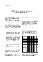
Compressor no.
Start no. Sy. 1
1
2 3 4 5 --
--
2
3 --
-- 1 --
--
--
--
--
--
14
--
Start no. Sy. 2
--
-- 1 2 --
--
--
--
--
--
Start no. Sy. 3
--
-- --
--
--
--
--
--
--
--
Start no. Sy. 4
--
-- --
--
--
--
--
--
--
--
Start no. Sy. 5
--
-- --
--
--
--
--
--
--
--
Start no. Sy. 6
--
-- --
--
--
--
--
--
--
--
Start no. Sy. 7
--
-- --
--
--
--
--
--
--
--
Start no. Sy. 8
--
-- --
--
--
--
--
--
--
--
Start no. Sy. 9
--
-- --
--
--
--
--
--
--
--
Start no. Sy. 10/A
--
-- --
--
--
--
--
--
--
--
Start no. Sy. 11/B
--
-- --
--
--
--
--
--
--
--
Start no. Sy. 12/C
--
-- --
--
--
--
--
--
--
--
Start no. Sy. 13/D
--
-- --
--
--
--
--
--
--
--
Start no. Sy. 14/E
--
-- --
--
--
--
--
--
--
--
In the example shown there are five com-
pressors, numbered 1 to 5 (each compressor
must be labelled to avoid confusion).
Summary of Contents for UNISAB S-Control
Page 1: ......


