background image

8

0171-761-EN

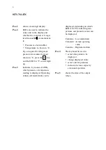
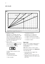
When the display light stops flashing,
automatic operation will be resumed.

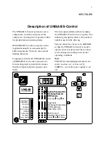
Operator panel

Pos. 1.

Display

Numbers 0 - 9

A decimal point

indicates that the

last digit is a

1/10 decimal

-- (minus) and/

or number 1

Pos. 2.

Unit indicator

LED

Bar

°

C

°

C sat

The LEDs indicate whether the compressor
is regulated manually or automatically and
the unit of the value displayed.

·

No light in the LED beside

indicates

that the UNISAB S-Control is operating
in

automatic

mode. A steady light indi-

cates that the UNISAB S-Control is ope-
rating in

manual

mode.

·

A light in the LED beside Bar or

°

C indi-

cates that the display is either Bar or

°

C

respectively. UNISAB S-Control can on-
ly display Bar and

°

C for the relevant re-

frigerant.

· °

C

sat

indicates that suction pressures, dis-

charge pressures and intermediate pres-
sures are shown in the corresponding
temperatures for saturated vapour. To
change from Bar to

°

C

sat

and vice versa

depress the

SET

key momentarily. Bar

values are displayed relative to atmo-
spheric pressure.

Pos. 3. LEDs for value points

Suction Pressure (SP)
Discharge Pressure
Diff. Pressure
Timer No.

Superheat
Discharge Temperature
Oil Temperature
Brine Temp. (SP)

Motor Current

Control

NZ

P. Band

Capacity Slide Position

Time

SP

*

*

*

The LED with a steady light indicates which
value is shown in the display. Obviously on-
ly one LED can be steady at any given time.

Except for the three lines above, which are
indicated by means of *, the three columns
in the LED field marked

,

¯

and

­

func-

tion as follows:

indicates the measuring point whose cur-
rent measuring value is displayed .

¯

indicates the low alarm limit of the mea-
suring point whose value is displayed

­

indicates the high alarm limit of the mea-
suring point whose value is displayed.

Summary of Contents for UNISAB S-Control

Page 1: ......

Page 2: ...1 0171 761 EN 94 06 Compressor type Shop no Refrigerant UNISAB Version no Instruction manual for UNISAB S Control Computerized control system for screw compressors...

Page 3: ...es sor motor must be switched off at the main switch to prevent the compressor from being started accidentally The UNISAB S Control box contains live parts which makes it absolutely necessary that you...

Page 4: ...Alarms 13 Low and high alarm limit settings 14 Factory settings for alarm limits 15 Reverting to factory settings for alarm limits 15 Warning limits 16 Configuration 17 Various functions 21 Feed back...

Page 5: ...acing parts 36 Trouble shooting 38 Appendix 40 Setting of pressure and temperature alarm limits 40 Actual warning and alarm limits 41 External wiring 0171 773 MULTISAB sequential regulation 0171 759 I...

Page 6: ...ollowing description refers to the position numbers used on the drawing Various values have been set by SABROE so that the UNISAB S Control is ready to operate when it is delivered These values can be...

Page 7: ...sat will light up Pos 3 indicates by means of LEDs which pressure or temperature reading is displayed Operating values and alarm limits can be displayed depending on which LED is lit The following te...

Page 8: ...alarm limits Therefore the UNISAB S Control is ready for operation When power has been connected the UNISAB S Control will be set to manu al operation If the display shows when you switch the UNISAB S...

Page 9: ...charge pressures and intermediate pres sures are shown in the corresponding temperatures for saturated vapour To change from Bar to Csat and vice versa depress the SET key momentarily Bar values are...

Page 10: ...e drop in the oil filter and with cold oil somewhat more TIMER NO TIME SP please refer to the chapter Timers 0 Hour counter hours x 10 number of operating hours 1 Start start 2 Stop start 3 Prelubrica...

Page 11: ...alarm limits are exceeded When the system is set to manual oper ation the keys are used to regulate the com pressor capacity The keys are used as follows are used to move from one column to another in...

Page 12: ...y light in the middle column of the top row indicates that the reading applies to measured suction pressure The LED for Bar is lit and the display shows 0 1 This means that the Suction Pressure is 0 1...

Page 13: ...l the digit to the far right of the display be gins to flash Pressing the key increases the value of the flashing digit Likewise pressing the key reduces the value of the flashing digit Then press the...

Page 14: ...ic reset and some by manual reset At manual reset the compressor can only start when the reason for stopping has been rectified and the actual value is once again within the warning limit and the RE S...

Page 15: ...mit the LED in the column for suction pressure and brine tempera ture are set points for regulation and not alarm limits Please refer to the section entitled Automatic operation If the low alarm limit...

Page 16: ...the low alarm limit the differential pressure alarm will be delayed 45 seconds after start up and during opera tion At the low alarm limit the superheat alarm is delayed 300 seconds after start up At...

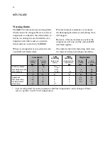
Page 17: ...he compressor will stop and the relevant LED will flash rapidly The white fields in the following table state the interval between warnings and alarms Low alarm Low High High alarm Limit for setting F...

Page 18: ...alid in configu ration mode Description of valid fields Suction pressure reading Discharge pressure reading Oil pressure reading These fields show a figure between 0 and 255 which relates to the measu...

Page 19: ...nt 20 C 150 C This parameter specifies the dis charge temperature above which the HLI BLI relay is energized If 100 is entered the function is dis abled 8 Economizer 0 No 1 Yes 9 Economizer 60 C 25 C...

Page 20: ...tion temperature calibration Discharge temperature calibration Oil temperature calibration Brine temperature calibration This field is used to calibrate the tempe rature measurements Usually it is not...

Page 21: ...values This field can be used to revert to factory values To do so press RE SET After a few seconds the display will show to indicate that the values have been changed This operation affects Alarm an...

Page 22: ...ails Oil flow switch If the oil flow switch is de energized for more than 10 sec during operation an alarm will be indicated AL4 will flash ra pidly in the display This alarm function will not be acti...

Page 23: ...process limits for suction pressure and capacity can be en tered Furthermore economizer operation can be selected Auxiliary output During configuration one of the following functions may be selected o...

Page 24: ...rol into con figuration mode Wait 10 15 seconds to allow all the measured values to settle The LED beside Suction Pressure in the column will light up and the measured pressure the atmospheric pressur...

Page 25: ...en done and the pro cedure for changing a parameter has been completed The UNISAB S Control will now display the correct motor current while the compressor is in operation It may be necessary to calib...

Page 26: ...ounter The following table shows timer numbers and indicates which timers will cause a LED to flash which timers can be edited etc The timers are described in the following section Timer No Descriptio...

Page 27: ...essure 1 0 bar 7 Slide max When the compressor stops the capacity will move towards 0 capacity If the capacity has not been reduced to under 5 within the period to which the timer has been set an alar...

Page 28: ...ulation which automatically regulate the compressor capacity It is possible to regu late the capacity manually or automatical ly Manual operation The following describes how to select ma nual compress...

Page 29: ...limiting functions please refer to the chapter Limiting functions are also active for manual operation Oil Pump When prelubrication is started manually the timer can be changed by pressing either the...

Page 30: ...y Use the LEDs beside Control NZ P Band to access the following functions Control is used to select the start sequen ce number and regulation system num ber The size of the field is as follows X X Y w...

Page 31: ...ation Settings The settings mentioned must be within the limits stated in the following table You can use the actual column to note the actual set tings The settings can be changed as de scribed in th...

Page 32: ...rises above the warning limit please refer to the section Warning limits the LED in the discharge pressure column will begin to flash and the compressor capacity will be reduced un til the discharge p...

Page 33: ...ission normal stop This function only applies in automatic operation It is not possible to start the compressor unless the input is energized If the compressor is in operation the ca pacity is reduced...

Page 34: ...hen the compressor is runnung at part load the Vi slide will automatically be moved to min or max position depending on the pressure conditions over the com pressor When the Vi slide is in max posi ti...

Page 35: ...s for regulating the complete system provided the system regulator is not exposed to a power cut If a power cut occurs the MULTISAB sys tem will promote the next compressor which will then control the...

Page 36: ...t sequence no 2 As an example system no 1 and 2 could be high pressure and booster system respec tively If there is a need for changing a compressor from one system to another the start sequence no an...

Page 37: ...he drawing illustrates the two locking pawls should be twisted to each side You can then pull the multiplug with the flat cable out of the socket Unscrew the 2 screws that fasten the cov er to the hin...

Page 38: ...been calibrated Select P Band and press the RE SET key to set the factory values FAC in the dis play Switch off the power supply to the UNISAB S Control Switch it on again right away and the UNISAB S...

Page 39: ...h the holes in the inside of the door If they are not lit replace the computer cover Coupling out due The measuring value must be within the alarm limits Check the measuring value If it is very high o...

Page 40: ...or termperature too high Thermistor or bridge not fitted or defective Display shows AL4 Oil flow switch Oil too cold Too much refrigerant in the oil foaming Insufficient oil in the oil separator Displ...

Page 41: ...differential pressure of 2 5 bar 1 0 bar however for SAB 128 163 in booster operation SAB 110 SAB 128 Mk2 and SAB 163 Mk2 Set low alarm to stop the compressor at a differential pressure of 0 bar Alway...

Page 42: ...lubri cating oil in the compressor instr manual 10 K High warning always 5 K lower than high alarm Set low alarm to stop the compressor at 20 C Low warning always 5 K higher than low alarm Actual war...

Reviews: