background image

www.SteamPoweredRadio.Com

Summary of Contents for 2000 DMM

Page 1: ...www SteamPoweredRadio Com sabtranics mt INTEANATIONAL INC P 0 0X 4 83 0A LAS TX 71152D U S A MODEL 20QODMM ASSEMBLY OPERATION MANUAL COPYRIGHT 1977 SABTRONICS I T L INC ALL RIGHTS RESERVED...

Page 2: ...0 power True RMS Kit Contains parts necessary to upgrade all AC functions from sine wave cali brated average sensing to true RMS Features a precalibrated laser trim ed high accuracy integrated circuit...

Page 3: ...instrunent equipped with rechargeable batteries 4 C cells will typically operate for 15 hours recharging using the AC Power Adapter takes approximately 16 hours If the batteries measure below 4 4V un...

Page 4: ...n junction with the AC and range switches to select voltage function AC or DC Works in conjunction with the AC and range s witches to select current function AC or DC Selects resistance measurement mo...

Page 5: ...www SteamPoweredRadio Com Ill C 0 t l 0 ro Ill c c c 0 0 0 0 0 a 5 q z C c c c o e 2 E c C fli 0...

Page 6: ...1N4148 8 i _ Transistor 2SC1849Q l o _ Transistor 2N4403 1 Transistor 2N4400 2 TRIAC T2500B 30 B 7 Resistor Wirewound l ohm 1 5 I l Resistor Carbon Film 100 ohm 5 1 41 7 1 Resistor Metal Film 105 ohm...

Page 7: ...R7 20 40 45 Resistor Carbon Film l0K 5 l 4W 4 R36 Resistor Carbon Pilm 16K 5 l 4W l R2 l Resistor Carbon Film 47K 5 l 2W 1 R4 Resistor Metal Film 97 6K 1 l 4W 1 R22 4 47 Resistor Carbon Film l00K 5 l...

Page 8: ...luf Capacitor Disc luf Capacitor Mylar 082uf sov Capacitor Mylar luf sov Capacitor Mylar 22uf sov Capacitor Elect l0uf 16V Capacitor Elect l00uf l0V Capacitor Elect l00uf 16V Capacitor Elect 220uf 16V...

Page 9: ...w Wire Stand Case Cable Ribbon 15 conductor Magnet Wire Buss W ire i122 Insulated W i r e White Insulated Wire Black Tape Black 1 4 iJe Screw 4 x 40 x 1 4 Self Tappin9 Screw 6 x 32 x l 3 4 Spacer Swit...

Page 10: ...he board to minimize this It is recommended that a 25 to 40 watt soldering iron be used with a tip small enough to allow easy soldering to the small IC pads but not so small that heat is not retained...

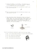
Page 11: ...e wire provideC j J l CJ J2 J 3 I J4 Ill JG ltl J3 J9 Install the follo1 ing jur ipers using the wh ite in iul11tec wi re provided DJ J7 fl JlS sfo Open the packet containing the resistors Set aside t...

Page 12: ...www SteamPoweredRadio Com J l u I to 1t 7 i 00 I t 7 13...

Page 13: ...he diode package and install eight 1N4148 diodes at the fol lowing locations NOTE POLARITY The polarity on these diodes i s difficult to read The red tape indicates cathode the white tape indicated an...

Page 14: ...3 4 64K 46 40 ohms 1 R27 536 ohm 1 wR30 121 ohm 1 u R29 1 21K 1210 ohm 1 Place the remaini ng precision resistors in their bag These will be installed later II Before proceeding with the switch assemb...

Page 15: ...ure until the board is seated 1 Solder all the pins on the s witch asse mbly tha t protrude through the P C board V After turning the P C board ove r so that the compone nt side faces up remove the tw...

Page 16: ...www SteamPoweredRadio Com 0 Figure 2...

Page 17: ...ace with a sharp blade or knife Do not cut any other way or damage to the socket will result d Insert the TS dInsert one points T2 4 pin strip 6 pin strip and T3 UT APART AT POINTS SHOWN into holes ma...

Page 18: ...arts and install integrated circuit Z4 into t he 8 pin socket as shown bel ow NOTE Z4 20 25 may be one of t wo types either an 8 pin dual in line package MC1 403 or a three lead transistor t ype AD580...

Page 19: ...ors Note Polarity flat 1 03 I 04 I j l Locate and install the two fuse c lips Note the fuse clips have a stop ridge This must face away from the fuse body Install the fuse into the fuse clips Install...

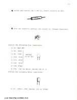
Page 20: ...citor package md install Cl Trimmer Capacitor Install the following Oise Capacitors II C2 24pf NPO II CS Oluf II C6 Oluf II Cl2 Oluf II Cl3 Oluf II Cl9 Oluf I I ClO 470pf M arked 01 or 103 II Cl8 luf...

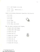
Page 21: ...Note Polarity l I C4 l0uf I I CB l0uf I I C9 l0uf II Cll 220uf J ClS l00uf l0V Cl6 l00uf 16V or 20V Open the packet containing nine trimpots II Install Rl6 l00K Trimpot I Install R28 l00K Trimpot I I...

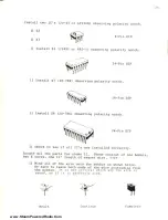
Page 22: ...t mounted on the bottom of the P C board II C20 082 Mylar 200V Capacitor l ltt D f 4 c I ll_ I C o u o _ oov If sockets for IC s are not used exercise care when soldering the IC pins Avoid excessive h...

Page 23: ...l Z6 20 786 observing polarity notch 2 4 Pin DIP Check to sec if all IC s are i nstalled correctly Locate all the parts for choke Ll These consist of one bobbin t wo E cores one 11 length of magnet wi...

Page 24: ...1 Wind several layers of tape around the cores to hold the assembly together J Scrape or sand insulation off choke leads J Cut strip and form a piece of black insulated wire and use the wire to hold L...

Page 25: ...ductors II Strip a nd solder the three conductor cable into the holes on the main P C board labeled DPl DP2 nP3 II Strip and solder one end of the five conductor cable into the holes labeled Digits 1...

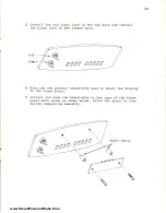
Page 26: ...he black jack in the common hole flIllIllIll Ill l117117Ill II Find the two plastic stand offs used to mount the display to the front panel Install and bond the stand offs to the rear of the front pan...

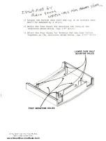
Page 27: ...at won t be damaged by a drill 11 Drill the four holes for mounting the feet at the locations shown below Use 1 8 drill Drill the four holes for holding the two case halves together at the locations s...

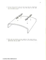
Page 28: ...feet to the case half by inserting the two shafts on each foot into the holes in the case half as shown below Melt the two shafts on the inside of the cover with a soldering iron to secure each foot...

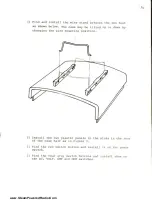
Page 29: ...be tilted up or down by changing the wi re mounting position Install the two plastic panels in the slots in the rear of the case half as in Figure 3 I Find the red switch button and install it on the...

Page 30: ...onto the two plastic stand offs on the rear of the front panel as previously shown Find the plastic battery holder with blue or black and red wires Install the red wire in the hole labeled and the bl...

Page 31: ...www SteamPoweredRadio Com SPLAY BOAR0 3 WIRE CABLE 5 WIRE CABLE 7 WIRE CABLE INPUT JACK GNO JA C K Figure 3 SWITCH ASSEMBLY SCREWS 4 MAIN PC BOARD BATTERY PACK PLASTIC PANEL 2 CASE BOTTOM t N t...

Page 32: ...ese numbers when used with the following calibration procedure will allow reasonably accurate calibration of the Model 2000 Z4 which is a voltage refer ence and the four resistors RJS R36 R37 and R38...

Page 33: ...roximately 1800 This ad justmen t calibrates the internal 2 volt reference voltage This completes the calibration of the t wo reference voltages used by the A D converter The following steps are used...

Page 34: ...Ohm and 1 megaohm 18 Remove the test wire from Test Point T2 and install in Test Point T4 While monitoring the display adjust R3 to obtain the calibr ation number E This will be approximately 1 800 No...

Page 35: ...Xl0 30 Install test l eads into the Model 2000 input jacks and measure the DC voltage across the l0uf capacitor in the peak detector circuit shown above Record this vo ltage This vol tage is ACpeak 3...

Page 36: ...Example HP3465A 3 AC Siqnal Generator l0V at l0Kllz SCOPE The 2 volt reference the 2 volt reference and the ohrn reference voltages arc all calibrated using the e x ternal 4 1 2 digit multimeter The i...

Page 37: ...ad to R28 wiper and ground lead to Test Point TlO GND 6 Adjust R28 trimmer until 4 1 2 digit meter measures 1 9999 volt 7 Depress Power Ohm and lOK switches 38 8 Short the input jacks with jumper as s...

Page 38: ...fy that RS RS a nd R3 are properl y set 23 Remove Jl2 from Test Points TS and T6 24 Remove Jl3 from Test Points T7 and TS 25 Adjust trimmer Rll until the 4 1 2 digit meter reads 10 000K ohm from Test...

Page 39: ...V 33 Apply a precision 10 00VAC l0KHz sinewave siqnal to the input j acks 3 4 Adjust trimmer capacitor Cl until the Model 2000 displays as close to 10 0SV as possible This gives the meter the best l i...

Page 40: ...Cl uG t t 4 I l lt T C TICtll J OHM S 21A n 1 l U OUT O ltll C YUl l UI IC COtil t iltTU t t t jf r o I i I I I I I I I tH 11 1 I I I UY I I u I 11111 I I I I I I 10 a n o AC DC I r Ottll t 10 I I I...

Page 41: ...erter as ohms Current Shunt s and Switching RlO through Rl3 form three c urrent shunt resistances In the amp mode current through the input terminal s produces a voltage drop ac ross the selected shun...

Page 42: ...opriate decimal point Over Voltage and Over Current Protection TRCl and zener diodes VRl and VR2 form a crowbar circuit which short out damaging current and voltages during the time it takes for the f...

Reviews: