SOUTHERN AVIONICS COMPANY
Model SA100 Dual
2-76
Theory of Operation, Radiobeacon
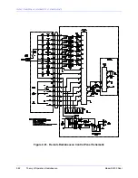
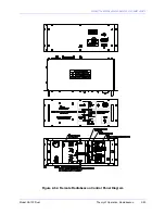
2.4.2 Radiobeacon Remote Control
Addition of remote control to the Radiobeacon Control System involves the installation of a
Remote Radiobeacon Control Panel at the remote control site, insertion of a Serial Interface
Board (SLP24300) and a Modem Board (SLP33600) within the Local Radiobeacon Control Panel
and connecting the Local and Remote Radiobeacon Control Panels to a suitable audio data link.
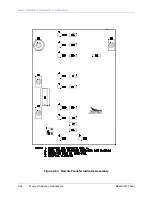
2.4.2.1 Serial Interface PWB
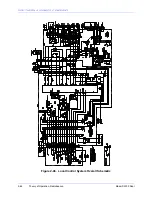
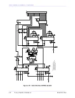
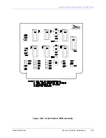
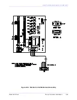
Radiobeacon Status signals from the Autotransfer Logic Board are applied to the Local Interface
PWB through the Local Control Motherboard circuitry. These signals which indicate the
transmitter and AC power supply status are applied in parallel to separate inputs of U1 and U2 of
the local Serial Interface PWB. U1 and U2 are special integrated circuits which encode the
parallel digital information applied to Pins 6, 7, 9 and 10 along with an address code programmed
with Pins 1, 2, 3, 4 and 5. The encoded binary bits are transmitted twice, as a serial bit stream,
from Pin 15 whenever Pin 14 of the integrated circuit is pulsed low. At the receiving end of the
data link, the binary bit stream is applied to receiving integrated circuits U3 and U4 of the remote
Serial Interface PWB where the bit stream is converted to parallel output signals at Pins 15, 14,
13, and 12. Each receiving integrated circuit is programmed with an address which corresponds
to the address of the corresponding transmitting integrated circuit on the Local Serial Interface
PWB. If the receiving integrated circuit senses a binary bit stream which incorporates its
programmed address, the rest of the binary bit pattern is stored in the integrated circuit. The next
bit stream which is sent is then compared with the one just received and if the two are identical
the data bits are applied to the output pins of the receiver integrated circuit. Because each
transmitter or receiver integrated circuit is capable of encoding or decoding four bits of data, two
transmitter integrated circuits are required at the transmitter site and two receiver integrated
circuits are required at the remote control for transmission of the eight bits of transmitter and AC
supply status. U5 and U6 apply alternating transmit enable pulses to U1 and U2 of the local
Serial Interface PWB. Control data received from the Remote Radiobeacon Control Panel is
applied to receiver integrated circuits U3 and U4 Pin 9. If two consecutive valid binary data
transmissions are received, the data is latched at the output Pins 15, 14, 13, and 12. These bits
then control Transmitter ON/OFF, Reset, and Primary Transmitter Select. U7 is an 8 channel
relay driver integrated circuit with high voltage open collector outputs. When the corresponding
switch is pressed on the remote panel, this generates a pull-down on the attached logic line,
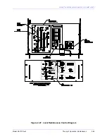
simulating the action of the local front panel control switch. To allow maintenance of the
equipment without interference from the remote panel, a Remote Disable switch is included on
the local control panel which shorts the incomming logic control signal from the remote panel.
This prevents the remote panel from changing the control settings but allows the status
indications to continue at the remote panel.
Note: Due to the data transmission rate, up to 5 seconds may be required to transmit a new
switch setting and receive acknowledgement from the local or remote panel. Press and hold
switches to be activated for the full 5 seconds or until a response is noted.
2.4.2.2 Modem PWB
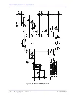
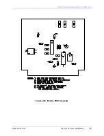
Transmission of the digital data stream between the Local Interface PWB and the Remote
Interface PWB requires conversion of the binary bit pattern from the DC logic signals used by the
transmitter and receiver integrated circuits to an audio frequency shift keyed signal suitable for
Summary of Contents for SA100
Page 20: ...SOUTHERN AVIONICS COMPANY Model SA100 Dual x Contents...
Page 22: ...SOUTHERN AVIONICS COMPANY Model SA100 Dual 1 2 Introduction This page intentionally left blank...
Page 25: ...SOUTHERN AVIONICS COMPANY Model SA100 Dual 1 5 Introduction Figure 1 2 Transmitter Portrait...
Page 26: ...SOUTHERN AVIONICS COMPANY Model SA100 Dual 1 6 Introduction This page intentionally left blank...
Page 28: ...SOUTHERN AVIONICS COMPANY Model SA100 Dual 1 8 Introduction This page intentionally left blank...
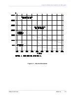
Page 119: ...SOUTHERN AVIONICS COMPANY Model SA100 Dual 3 3 Antennas Figure 3 1 Antenna Reactance...
Page 120: ...SOUTHERN AVIONICS COMPANY Model SA100 Dual 3 4 Antennas This page intentionally left blank...
Page 160: ...SOUTHERN AVIONICS COMPANY Model SA100 Dual 5 8 Maintenance This page intentionally left blank...
Page 162: ...SOUTHERN AVIONICS COMPANY Model SA100 Dual 6 2 Parts List This page intentionally left blank...
Page 164: ...SOUTHERN AVIONICS COMPANY Model SA100 Dual 6 4 Parts List This page intentionally left blank...
Page 218: ...SOUTHERN AVIONICS COMPANY Model SA100 Dual 6 58 Parts List This page intentionally left blank...

