SOUTHERN AVIONICS COMPANY
Model SA100 Dual
3-2
Antennas
Ideally, this antenna should be in a clear area; however, this is very seldom feasible on offshore
structures. Large obstacles close to the antenna will affect the directional properties and the
tuning of the antenna. If possible, the antenna should be installed with a clear area in the
direction of the most traffic.
The Mast Antenna is electrically very similar to a 200 pF capacitor in series with a small resistor.
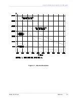
See the figure at the end of this section for a plot of the capacitive reactance.
3.2 “H” Antenna
The "H" Antenna is used on the helipad of offshore structures where there is no clear area to
install the Mast Antenna. It is a wire structure that is installed on the perimeter of the helipad.
The transmitter is mounted directly beneath it so that the vertical portion of the antenna is
the offshore structure itself. Electrical characteristics vary, depending mostly on the size of the
helipad but are generally similar to the Mast Antenna. Range is also comparable with the Mast
in most cases.
3.3 50-Foot Guyed Mast Antenna
This antenna is a guyed vertical monopole with capacitive top loading that was designed for land
installations where space is limited. The capacitive top hat consists of six 8-foot radials. The
counterpoise system consists of sixteen 60-foot radials made of #10 copper wire with 6-foot
ground rods at each end and one in the center. The antenna is guyed at the top and center.
The calculated range with the Guyed Mast Antenna exceeds the Mast Antenna but is less than
the "T" Antenna under the same conditions. This antenna is recommended for land
installation where space does not permit use of the "T" Antenna.
The Guyed Mast Antenna is electrically very similar to a 300 pF capacitor in series with a small
resistor. See the figure at the end of this section for a plot of the capacitive reactance.
3.4 Symmetrical “T” Antenna
The Symmetrical "T" Antenna is recommended if sufficient land is available. This antenna
requires a plot of ground approximately 150 feet by 350 feet.
The calculated range with the "T" Antenna and this transmitter for most locations in the
United States and with one of the lower priced ADF's is from 80 to 100 miles except over low
conductivity ground.
These range figures are for the standard "T" Antenna with a height of 55 to 60 feet. A long range
"T" Antenna with a height of 80 to 85 feet has a range of 100 to 120 miles. If even more range
is desired, SAC can supply "T" Antennas with heights up to 200 feet.
The standard "T" is electrically very similar to a 1000 pF capacitor in series with a small resistor.
See Figure “Antenna Reactance,” on page 3-3 for a plot of the capacitive reactance.
Summary of Contents for SA100
Page 20: ...SOUTHERN AVIONICS COMPANY Model SA100 Dual x Contents...
Page 22: ...SOUTHERN AVIONICS COMPANY Model SA100 Dual 1 2 Introduction This page intentionally left blank...
Page 25: ...SOUTHERN AVIONICS COMPANY Model SA100 Dual 1 5 Introduction Figure 1 2 Transmitter Portrait...
Page 26: ...SOUTHERN AVIONICS COMPANY Model SA100 Dual 1 6 Introduction This page intentionally left blank...
Page 28: ...SOUTHERN AVIONICS COMPANY Model SA100 Dual 1 8 Introduction This page intentionally left blank...
Page 119: ...SOUTHERN AVIONICS COMPANY Model SA100 Dual 3 3 Antennas Figure 3 1 Antenna Reactance...
Page 120: ...SOUTHERN AVIONICS COMPANY Model SA100 Dual 3 4 Antennas This page intentionally left blank...
Page 160: ...SOUTHERN AVIONICS COMPANY Model SA100 Dual 5 8 Maintenance This page intentionally left blank...
Page 162: ...SOUTHERN AVIONICS COMPANY Model SA100 Dual 6 2 Parts List This page intentionally left blank...
Page 164: ...SOUTHERN AVIONICS COMPANY Model SA100 Dual 6 4 Parts List This page intentionally left blank...
Page 218: ...SOUTHERN AVIONICS COMPANY Model SA100 Dual 6 58 Parts List This page intentionally left blank...

