SOUTHERN AVIONICS COMPANY
Model SA100 Dual
4-5
Installation and Operation
4.2 Local Radiobeacon Control Unit
The Local Radiobeacon Control Unit is unit 5 in the SSC or SA Series dual transmitter system.
1. Set the power switch on the Local Radiobeacon Control Panel to OFF, and ensure that all
input power has been removed.
2. Unfasten the four screws holding the front panel closed to expose the motherboard and card
assembly.
3. Check each of the printed wiring boards and relays to insure that they are fully seated.
4. Check the supply voltage programming switch on the Autotransfer Logic Board and set it to
115 VAC or 230 VAC to correspond to the transmitter AC primary supply voltage.
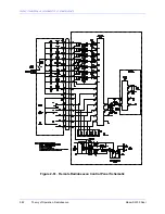
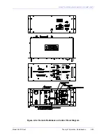
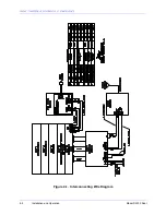
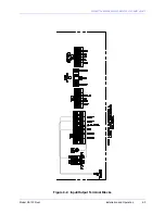
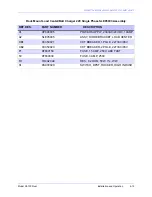
5. Refer to figures "Local Radiobeacon Control Unit Overall Schematic," Input/Output Terminal
Blocks," and the "Interconnecting Wire Diagram" to make necessary electrical connections.
6. Refer to sections "Transmitter Installation" and "Coupler Setup" and complete.
7. Complete Antenna Tune-Up Section. To apply AC power to the transmitter in step 2, place
the Local Radiobeacon Control Panel power switch in the ON position. The following
initializing steps may also be required.
8. Press the Primary Transmitter Select switch to the Transmitter 1 position. Press the
Transmitter ON/OFF switch to the ON position. Press the Reset pushbutton on the Local
9. Radiobeacon Control Panel.
10. Complete Transmitter Tune-Up Section.
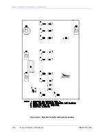
11. Attach the Serial Data Link to terminals 1, 2 and 3 on the Remote Control terminal block
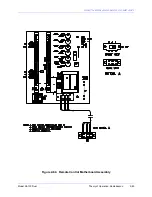
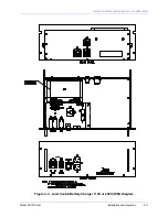
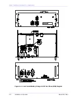
located on the Local Control Motherboard. See figure "Local Control Motherboard Diagram."
12. Leave power applied to the Local Radiobeacon Control Panel while installing the Remote
Radiobeacon Control Panel. Place the Remote Enable switch in the ENABLE position.
NOTE:
DC current flowing in the Serial Data Link must not exceed 3 mA or saturation of the
Modem coupling transformer will occur. If current exceeds 3 mA DC, install a DC blocking
capacitor in the data link.
4.3 Remote Radiobeacon Control Panel
1. Check the supply voltage programming switch on the Remote Control Motherboard and set it
to 115 VAC or 230 VAC to correspond to the available AC supply voltage.
2. If the optional modem PWB is used, attach the Serial Data Link to terminals 1 and 2 (Tip and
Ring) of Line Input terminal block TB1. This is located on the Remote Motherboard.
NOTE:
DC current flowing in the Serial Data Link must not exceed 3 mA or saturation of the
Modem coupling transformer will occur. If current exceeds 3 mA DC, install a DC blocking
capacitor in the data link.
Summary of Contents for SA100
Page 20: ...SOUTHERN AVIONICS COMPANY Model SA100 Dual x Contents...
Page 22: ...SOUTHERN AVIONICS COMPANY Model SA100 Dual 1 2 Introduction This page intentionally left blank...
Page 25: ...SOUTHERN AVIONICS COMPANY Model SA100 Dual 1 5 Introduction Figure 1 2 Transmitter Portrait...
Page 26: ...SOUTHERN AVIONICS COMPANY Model SA100 Dual 1 6 Introduction This page intentionally left blank...
Page 28: ...SOUTHERN AVIONICS COMPANY Model SA100 Dual 1 8 Introduction This page intentionally left blank...
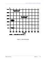
Page 119: ...SOUTHERN AVIONICS COMPANY Model SA100 Dual 3 3 Antennas Figure 3 1 Antenna Reactance...
Page 120: ...SOUTHERN AVIONICS COMPANY Model SA100 Dual 3 4 Antennas This page intentionally left blank...
Page 160: ...SOUTHERN AVIONICS COMPANY Model SA100 Dual 5 8 Maintenance This page intentionally left blank...
Page 162: ...SOUTHERN AVIONICS COMPANY Model SA100 Dual 6 2 Parts List This page intentionally left blank...
Page 164: ...SOUTHERN AVIONICS COMPANY Model SA100 Dual 6 4 Parts List This page intentionally left blank...
Page 218: ...SOUTHERN AVIONICS COMPANY Model SA100 Dual 6 58 Parts List This page intentionally left blank...

