


SOUTHERN AVIONICS COMPANY
Model SA100 Dual
4-7
Installation and Operation
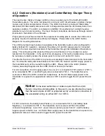
4.4 Load Center Battery Chargers (Optional)
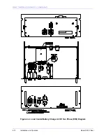
We have two versions of the 24VDC Load Center/Battery Charger. For dual transmitters we use
the rack mount (built-in) version because the dual configuration of the SA series transmitter has
an extra 19" rack mount space within it's enclosure for this purpose. The outdoors (stand-alone)
version of the 24VDC Load Center/Battery Charger is for use with single configuration SA series
transmitters because they do not have an additional drawer space.
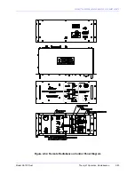
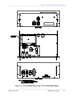
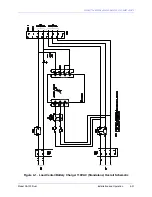
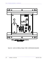
4.4.1 Rack Mount Load Center/Battery Charger Theory of
Operation
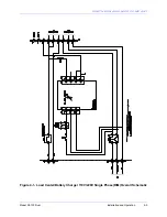
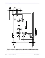
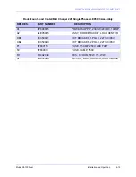
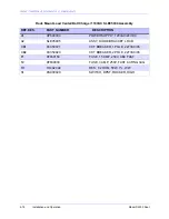
There are currently three assemblies of the 24V Load Center Battery Charger. There is one for
220V single-phase power systems, which maintains an unfused and unbroken neutral and
ground line. The two-phase 220V U.S. version fuses and breaks both line and neutral wires
while maintaining an unbroken ground line. The 110V U.S. version is similar to the two-phase
220V. The 110V version has a different power supply and convenience outlet. The system is
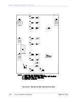
modular by design from the Circular Plastic Connectors "CPC" to the DIN rail mounted power
supply. The Power Supply may be removed for ease of maintenance or replacement, and the
CPC’s may be used as a troubleshooting aid. The CPC’s may be used to disconnect either the
transmitter connection, the DC input connection or both to isolate a fault to the drawer level.
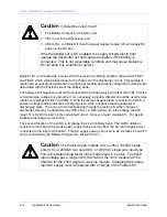
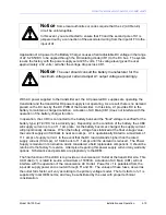
The AC input is applied to A1 "Power Supply" via the appropriate fuse or fuses, depending on
assembly, through the front panel switch S1 and Plug P6. The Power Supply is adjustable from
22.5 - 28.5VDC by adjusting the potentiometer clearly marked. Adjust 22.5-28.5V, on the front of
the Power Supply. The system leaves the factory with the power Supply set at 28.5V. This
voltage level gives the user approximately 2.32V/cell after the voltage drop across CR1.
However, the user should consult the battery manufacturer for the maximum voltage per cell and
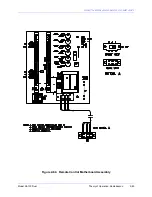
adjust the Power Supply output voltage accordingly. An isolation diode, CR1, has been added to
isolate the batteries from the power supply during loss of AC and initial installation. Resistor R1
serves as a battery Charge and Discharge Current sample resistor. This sample output is not
used in all transmitter system applications. The power supply is rated at 11.1A and will foldback
its output current if this limit is exceeded.
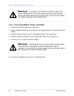
Warning!
Connecting the AC and DC input power circular plastic
connectors to the wrong jack will cause catastrophic damage to
equipment. Ensure the AC (J3) plug is mated to the three pin jack and
the DC (J4) plug is connected to the two pin jack.
Summary of Contents for SA100
Page 20: ...SOUTHERN AVIONICS COMPANY Model SA100 Dual x Contents...
Page 22: ...SOUTHERN AVIONICS COMPANY Model SA100 Dual 1 2 Introduction This page intentionally left blank...
Page 25: ...SOUTHERN AVIONICS COMPANY Model SA100 Dual 1 5 Introduction Figure 1 2 Transmitter Portrait...
Page 26: ...SOUTHERN AVIONICS COMPANY Model SA100 Dual 1 6 Introduction This page intentionally left blank...
Page 28: ...SOUTHERN AVIONICS COMPANY Model SA100 Dual 1 8 Introduction This page intentionally left blank...
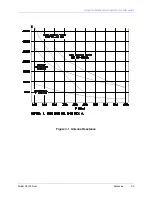
Page 119: ...SOUTHERN AVIONICS COMPANY Model SA100 Dual 3 3 Antennas Figure 3 1 Antenna Reactance...
Page 120: ...SOUTHERN AVIONICS COMPANY Model SA100 Dual 3 4 Antennas This page intentionally left blank...
Page 160: ...SOUTHERN AVIONICS COMPANY Model SA100 Dual 5 8 Maintenance This page intentionally left blank...
Page 162: ...SOUTHERN AVIONICS COMPANY Model SA100 Dual 6 2 Parts List This page intentionally left blank...
Page 164: ...SOUTHERN AVIONICS COMPANY Model SA100 Dual 6 4 Parts List This page intentionally left blank...
Page 218: ...SOUTHERN AVIONICS COMPANY Model SA100 Dual 6 58 Parts List This page intentionally left blank...