SOUTHERN AVIONICS COMPANY
Model SA100 Dual
4-17
Installation and Operation
4.4.2 Outdoors (Standalone) Load Center/Battery Charger Theory
of Operation
The Load Center / Battery Charger (LCBC) unit is an auxiliary part of the SA25-200 AC/DC
Transmitter system. The unit is comprised of an AC and a DC circuit breaker, a battery charger
module, and control and protection circuitry. The LCBC functions to provide AC Main safety
disconnect, DC Main safety disconnect, and to charge and maintain the 24V battery bank in an
operable condition. The LCBC is contained in a NEMA 3R, weather proof, raintight housing
suitable for out of doors mounting. The Input / Output connections are made up through conduit
knockouts in the bottom of the enclosure.
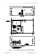
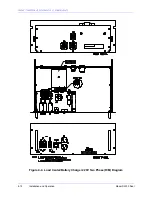
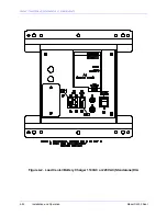
Proper planning must be exercised in the equipment mounting plan to ensure the LCBC unit is
properly mounted to maintain its weatherproof integrity. Please refer to the LCBC Outline
Diagram for mounting dimensions.
The LCBC provides three functions to supplement the transmitter system when configured for
battery backed DC operation. Generally, the primary AC and DC supply power is connected
directly to the main input terminal block of the transmitter through the installation infrastructure
wiring. This wiring should be protected through a circuit breaker or fuse located in a panel
remote from the transmitter. In the event of an emergency, or for routine maintenance, it would
be necessary to rapidly access the remote panel to remove AC and/or DC mains.
Thus the first function of the LCBC is to provide a local safety mains disconnect to the transmitter
set. To utilize the safety disconnect feature of the LCBC, the main AC and DC supply power to
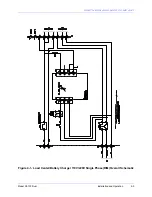
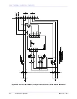
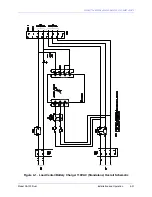
the transmitter set must be routed through the LCBC. Please refer to the LCBC (Outdoor
Version) Assembly Diagram and the LCBC (Outdoor Version) Schematic.
For AC connections, the AC supply power Line one (L1) is connected to TB1 position 1 (TB1.1),
L2 is connected to TB1.2, and Earth (ground) is connected to TB1.3. The transmitter set is
sourced via TB2 of the LCBC connected respectively. As the AC Main supply power to the
transmitter is required to be applied and removed, CB1 is used to toggle the AC power On and
Off.
For DC connections, the battery bank Positive (+) is connected to TB1.6, and battery bank
Negative (-) is connected to TB1.5. The transmitter set is sourced via TB2 of the LCBC
connected respectively. Loss of AC power removes primary power from A1, and the battery
supplies power to the DC bus. As the DC Main supply power to the transmitter is required to be
applied and removed, CB2 is used to toggle the DC power On and Off.
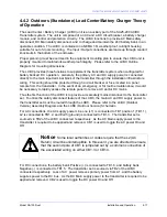
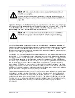
Notice
Some local authorities or codes require that the L2 (AC
Return) circuit be uninterruptible. In this event, you are directed to ensure
that the second pole of CB1 is jumpered out by a common connection of
the associated wiring on either CB1.3 or CB1.4.
Summary of Contents for SA100
Page 20: ...SOUTHERN AVIONICS COMPANY Model SA100 Dual x Contents...
Page 22: ...SOUTHERN AVIONICS COMPANY Model SA100 Dual 1 2 Introduction This page intentionally left blank...
Page 25: ...SOUTHERN AVIONICS COMPANY Model SA100 Dual 1 5 Introduction Figure 1 2 Transmitter Portrait...
Page 26: ...SOUTHERN AVIONICS COMPANY Model SA100 Dual 1 6 Introduction This page intentionally left blank...
Page 28: ...SOUTHERN AVIONICS COMPANY Model SA100 Dual 1 8 Introduction This page intentionally left blank...
Page 119: ...SOUTHERN AVIONICS COMPANY Model SA100 Dual 3 3 Antennas Figure 3 1 Antenna Reactance...
Page 120: ...SOUTHERN AVIONICS COMPANY Model SA100 Dual 3 4 Antennas This page intentionally left blank...
Page 160: ...SOUTHERN AVIONICS COMPANY Model SA100 Dual 5 8 Maintenance This page intentionally left blank...
Page 162: ...SOUTHERN AVIONICS COMPANY Model SA100 Dual 6 2 Parts List This page intentionally left blank...
Page 164: ...SOUTHERN AVIONICS COMPANY Model SA100 Dual 6 4 Parts List This page intentionally left blank...
Page 218: ...SOUTHERN AVIONICS COMPANY Model SA100 Dual 6 58 Parts List This page intentionally left blank...

