SOUTHERN AVIONICS COMPANY
Model SA100 Dual
4-18
Installation and Operation
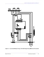
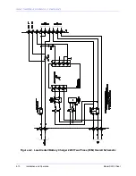
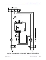
Resistor R1 is connected as a series shunt to provide a metering sample voltage out to TB2.7
and TB2.8, which will be proportional to the charge and the discharge current. This sample is
referenced at near ground potential to avoid the potentially hazardous voltage and current levels
associated with the Positive side of the battery bank.
The battery bank Negative must not be connected to ground at any point other than TB1.5 for the
current sample voltage to be produced. As necessary, a digital voltmeter should be used to take
reference readings at TB2.7 and TB2.8. With the meter's negative lead connected to TB2.8, a
positive voltage reading indicates a charging state, while a negative reading indicates a
discharging state. The amount of current passing through the resistor in either charge or
discharge state may be determined by Ohms law, i.e. E/R=I where: E is the voltage read on
meter, R is .02 Ohms and I is the calculated current. Hence, a meter reading of (- .16) would
indicate a discharge current of 8A.
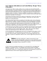
The second function of the LCBC is to charge the 24 volt battery bank. The LCBC utilizes a
constant current, switching mode power supply that is sourced from the AC main supply power
connected to the input of the LCBC. This AC supply power is sourced to A1 via fuses F2 and F3
and is controlled by the Battery Charger On / Off switch (S1).
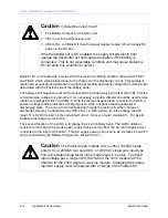
Caution
It should be noted, that if:
1 The Battery Charger is turned On, and
2 CB1 is set in the Off position, and
3 CB2 is On / or CB2 is Off. then the power Supply module (A1) will supply DC
power to the DC bus.
If the transmitter set is DC enabled, the supply will attempt to both
operate the transmitter set and charge the battery if the battery is
connected. This is not a desirable condition and may cause problems.
Do not allow this condition to persist.
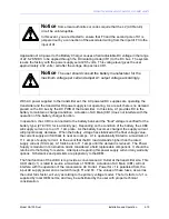
Caution
The Power Supply module (A1) is either 120VAC single
pole (US), or 230VAC two pole (US), or 230 VAC single pole input type.
This is the determining factor of the model used in service. The fixed
input voltage has a range of 93-132VAC for the 120V model and 187-
264VAC for the 230V single or two pole models. Changing the primary
input AC supply must correspond with a change of the model of A1.
Summary of Contents for SA100
Page 20: ...SOUTHERN AVIONICS COMPANY Model SA100 Dual x Contents...
Page 22: ...SOUTHERN AVIONICS COMPANY Model SA100 Dual 1 2 Introduction This page intentionally left blank...
Page 25: ...SOUTHERN AVIONICS COMPANY Model SA100 Dual 1 5 Introduction Figure 1 2 Transmitter Portrait...
Page 26: ...SOUTHERN AVIONICS COMPANY Model SA100 Dual 1 6 Introduction This page intentionally left blank...
Page 28: ...SOUTHERN AVIONICS COMPANY Model SA100 Dual 1 8 Introduction This page intentionally left blank...
Page 119: ...SOUTHERN AVIONICS COMPANY Model SA100 Dual 3 3 Antennas Figure 3 1 Antenna Reactance...
Page 120: ...SOUTHERN AVIONICS COMPANY Model SA100 Dual 3 4 Antennas This page intentionally left blank...
Page 160: ...SOUTHERN AVIONICS COMPANY Model SA100 Dual 5 8 Maintenance This page intentionally left blank...
Page 162: ...SOUTHERN AVIONICS COMPANY Model SA100 Dual 6 2 Parts List This page intentionally left blank...
Page 164: ...SOUTHERN AVIONICS COMPANY Model SA100 Dual 6 4 Parts List This page intentionally left blank...
Page 218: ...SOUTHERN AVIONICS COMPANY Model SA100 Dual 6 58 Parts List This page intentionally left blank...

