SOUTHERN AVIONICS COMPANY
Model SA100 Dual
4-19
Installation and Operation
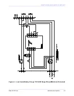
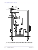
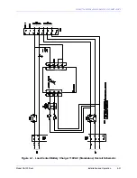
Application of AC power to the Battery Charger causes a field adjustable DC voltage in the range
of 22.5-28.5VDC to be applied through the DC isolating diode (CR1) to the DC bus. The system
leaves the factory with the power supply set at 28.5 volts. This voltage level gives the user
approximately 2.32 volts / cell after the voltage drop across CR1.
With AC power supplied to the transmitter set, the AC powered DC supplies are operating the
transmitter and the transmitter DC power supply is not operating. As a result, there is no demand
placed on the DC bus by the DC PWB of the transmitter. In this state, A1 provides DC to the
battery to maintain a charged condition. Actuation of AC Main (CB1) does not interfere with the
operation of the battery charger function.
In operation, the LCBC is connected to the battery bank and the "float" voltage is verified for the
battery type; (27.8 VDC for lead acid type). Depending on the condition of the battery, the LCBC
will supply current up to an 11.1 amp rate. As the battery becomes charged, the supply current
will proportionally decrease. When the battery voltage has stabilized at the float voltage value,
the current supply will fold back to near zero amps. A1 is operationally limited to a maximum of
11.1 amps of supply current. In the event that the DC load demands higher than the rated
supply current (10 Amps), A1 folds back to 11.1 amps until the demand is reduced. The Power
Supply is modular in construction and is considered a field replaceable component. It should be
returned to the factory for service. Attempts at repairing this power supply will void any warranty
options. Schematics and parts lists are proprietary to the OEM.
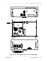
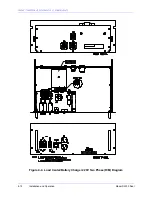
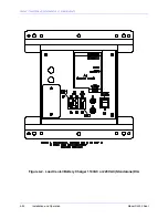
The final function of the LCBC is to provide a convenience AC Outlet at the transmitter site. This
AC Outlet (J1) is rated to source a maximum of 1800VA. Actuation of AC Main (CB1) will not
interfere with the operation of the convenience AC Outlet. Power for J1 is paralleled from the
input AC supply power and is routed through F1 and F4. The values of these fuses, as well as
the outlet form factor, will vary according to the primary voltage model. The form factor of J1 is
supplied by local OEM norms, and may be substituted by the user with proper technical
consideration.
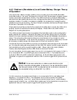
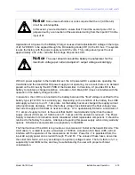
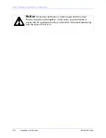
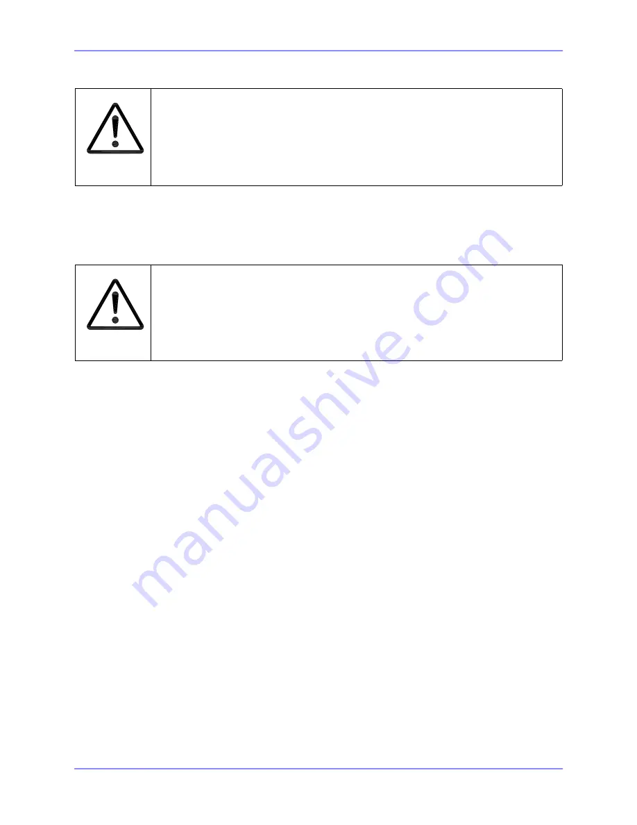
Notice
Some local authorities or codes require that the L2 (AC Return)
circuit be uninterruptible.
In this event, you are directed to ensure that F3 and the second pole of S1 is
jumpered out by a connection of the associated wiring from the input of F3 to the
input of A1.
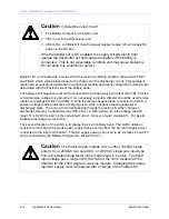
Notice
The user should consult the battery manufacturer for the
maximum voltage per cell and adjust A1 output voltage accordingly.
Summary of Contents for SA100
Page 20: ...SOUTHERN AVIONICS COMPANY Model SA100 Dual x Contents...
Page 22: ...SOUTHERN AVIONICS COMPANY Model SA100 Dual 1 2 Introduction This page intentionally left blank...
Page 25: ...SOUTHERN AVIONICS COMPANY Model SA100 Dual 1 5 Introduction Figure 1 2 Transmitter Portrait...
Page 26: ...SOUTHERN AVIONICS COMPANY Model SA100 Dual 1 6 Introduction This page intentionally left blank...
Page 28: ...SOUTHERN AVIONICS COMPANY Model SA100 Dual 1 8 Introduction This page intentionally left blank...
Page 119: ...SOUTHERN AVIONICS COMPANY Model SA100 Dual 3 3 Antennas Figure 3 1 Antenna Reactance...
Page 120: ...SOUTHERN AVIONICS COMPANY Model SA100 Dual 3 4 Antennas This page intentionally left blank...
Page 160: ...SOUTHERN AVIONICS COMPANY Model SA100 Dual 5 8 Maintenance This page intentionally left blank...
Page 162: ...SOUTHERN AVIONICS COMPANY Model SA100 Dual 6 2 Parts List This page intentionally left blank...
Page 164: ...SOUTHERN AVIONICS COMPANY Model SA100 Dual 6 4 Parts List This page intentionally left blank...
Page 218: ...SOUTHERN AVIONICS COMPANY Model SA100 Dual 6 58 Parts List This page intentionally left blank...

