


SOUTHERN AVIONICS COMPANY
Model SA100 Dual
4-27
Installation and Operation
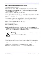
4.5 Initial Transmitter Setup
1. Connect transmitter RF out to a suitable 50 Ohm non-inductive dummy load. Each
transmitter has an internal 50 Ohm load for test purposes. To use the internal dummy load
connect the jumper on TB3 to the dummy load position, see figure "Transmitter Diagram SA
Series Rack Mount Spain."
2. Locate and verify frequency programming of the SPA Filter PWB(s), see figures "Filter PWB
Schematic, "Filter PWB Diagram," "Filter PWB Jumper Detail."
3. Check the frequency set with the programming switches on the KWOSYN PWB. The
frequency is read directly on the rotary switches. Jumper J1 adds 0.5 KHz if it is closed.
Check that S1 is in the C1 position if the frequency is between 190 and 320 KHz and in the
C2 position if the frequency is between 320 and 535 KHz.
4. Check that the jumper on the Tone Key PWB is in the correct position for the tone frequency.
See figure "Tone Key PWB Schematic" and "Tone Key PWB Diagram."
5. Check that the correct identification code is programmed on the Coder Shift Register
PWB(s). See figure "Example Program for Coder Shift Register PWB."
6. Set RF LEVEL and MOD to full CCW.
7. Set MODE Switch to CARR.
8. Set MONITOR switch to DSBL.
9. Set RF METER switch to FRWD.
10. Set PA READ to VOLTAGE.
11. For multiple RF Groups, set PA SELECT to 1.
12. For a dual system, complete steps 1 through 11 for both transmitters.
1
Summary of Contents for SA100
Page 20: ...SOUTHERN AVIONICS COMPANY Model SA100 Dual x Contents...
Page 22: ...SOUTHERN AVIONICS COMPANY Model SA100 Dual 1 2 Introduction This page intentionally left blank...
Page 25: ...SOUTHERN AVIONICS COMPANY Model SA100 Dual 1 5 Introduction Figure 1 2 Transmitter Portrait...
Page 26: ...SOUTHERN AVIONICS COMPANY Model SA100 Dual 1 6 Introduction This page intentionally left blank...
Page 28: ...SOUTHERN AVIONICS COMPANY Model SA100 Dual 1 8 Introduction This page intentionally left blank...
Page 119: ...SOUTHERN AVIONICS COMPANY Model SA100 Dual 3 3 Antennas Figure 3 1 Antenna Reactance...
Page 120: ...SOUTHERN AVIONICS COMPANY Model SA100 Dual 3 4 Antennas This page intentionally left blank...
Page 160: ...SOUTHERN AVIONICS COMPANY Model SA100 Dual 5 8 Maintenance This page intentionally left blank...
Page 162: ...SOUTHERN AVIONICS COMPANY Model SA100 Dual 6 2 Parts List This page intentionally left blank...
Page 164: ...SOUTHERN AVIONICS COMPANY Model SA100 Dual 6 4 Parts List This page intentionally left blank...
Page 218: ...SOUTHERN AVIONICS COMPANY Model SA100 Dual 6 58 Parts List This page intentionally left blank...