SOUTHERN AVIONICS COMPANY
Model SA100 Dual
1-9
Introduction
1.4 Specifications: Automatic Transfer Unit SA Series
1.4.1 Local Radiobeacon Control
CONTROL FUNCTIONS: TRANSMITTER ON/OFF, PRIMARY TRANSMITTER SELECT,
RESET TO PRIMARY, NORMAL/TEST, REMOTE DISABLE, AUDIO ALARM ENABLE/
DISABLE, POWER.
INDICATORS: TRANSMITTER ON, PRIMARY TRANSMITTER (TRANSMITTER 1/
TRANSMITTER 2), SYSTEM STATUS (PRIMARY: Selected primary transmitter operating,
SECONDARY: Selected primary transmitter failed and secondary transmitter operating, FAIL:
Both transmitters failed). AUDIO ALARM (Alarms whenever system status is FAIL). REMOTE
CONTROL LINK UPDATE (Flashes whenever the optional REMOTE RADIOBEACON
CONTROL PANEL supplies a control update). VOICE indicates handset activated. DATA
indicates handset switched off.
POWER: With "TRANSMITTER ON" selected: AC power 115/230 VAC ±20% 50/60 Hz, 12 VA
maximum or 24 VDC, 700 mA maximum. With "TRANSMITTER OFF" selected: DC power
requirements 24 VDC, 40 mA maximum.
CIRCUIT PROTECTION: Fuses are furnished in AC and DC power lines. Control link is
transformer isolated by signal transformer meeting MIL-T-27D specifications and 1000 VRMS
insulation test voltage. Logic line inputs are isolated by series impedances and diode clamps.
OPERATING CONDITIONS: Continuous unattended operation in the following environments:
ambient temperature -50 degrees C to 70 degrees C, relative humidity 0 to 100% without
condensing moisture.
INSTALLATION REQUIREMENTS: The LOCAL RADIOBEACON CONTROL in housed within
the transmitter enclosure. The front panel height is 7 inches.
REMOTE CONTROL: Remote operation can be achieved by installation of a SERIAL
INTERFACE PWB and MODEM PWB within the LOCAL RADIOBEACON CONTROL PANEL,
installation of a REMOTE RADIOBEACON CONTROL PANEL at the remote control site, and
installation of a suitable remote control datalink. Loss of signal from the control link or REMOTE
RADIOBEACON CONTROL PANEL will not affect radiobeacon transmission
1.4.2 Remote Radiobeacon Control Panel
CONTROL FUNCTIONS: TRANSMITTER ON/OFF, PRIMARY TRANSMITTER SELECT,
RESET TO PRIMARY, AUDIO ALARM ENABLE/DISABLE, POWER.
INDICATORS: TRANSMITTER ON, AC POWER present (at transmitter site), PRIMARY
TRANSMITTER (TRANSMITTER 1/TRANSMITTER 2) SYSTEM STATUS (PRIMARY,
SECONDARY, FAIL), REMOTE CONTROL ENABLE, REMOTE CONTROL LINK UPDATE.
VOICE indicates handset activated. DATA indicates handset switched off.
POWER: 115/230 VAC ±20% 50/60 Hz 5VA.
Summary of Contents for SA100
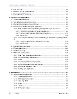
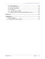
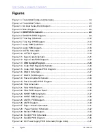
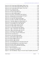
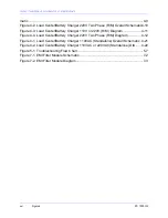
Page 20: ...SOUTHERN AVIONICS COMPANY Model SA100 Dual x Contents...
Page 22: ...SOUTHERN AVIONICS COMPANY Model SA100 Dual 1 2 Introduction This page intentionally left blank...
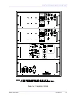
Page 25: ...SOUTHERN AVIONICS COMPANY Model SA100 Dual 1 5 Introduction Figure 1 2 Transmitter Portrait...
Page 26: ...SOUTHERN AVIONICS COMPANY Model SA100 Dual 1 6 Introduction This page intentionally left blank...
Page 28: ...SOUTHERN AVIONICS COMPANY Model SA100 Dual 1 8 Introduction This page intentionally left blank...
Page 119: ...SOUTHERN AVIONICS COMPANY Model SA100 Dual 3 3 Antennas Figure 3 1 Antenna Reactance...
Page 120: ...SOUTHERN AVIONICS COMPANY Model SA100 Dual 3 4 Antennas This page intentionally left blank...
Page 160: ...SOUTHERN AVIONICS COMPANY Model SA100 Dual 5 8 Maintenance This page intentionally left blank...
Page 162: ...SOUTHERN AVIONICS COMPANY Model SA100 Dual 6 2 Parts List This page intentionally left blank...
Page 164: ...SOUTHERN AVIONICS COMPANY Model SA100 Dual 6 4 Parts List This page intentionally left blank...
Page 218: ...SOUTHERN AVIONICS COMPANY Model SA100 Dual 6 58 Parts List This page intentionally left blank...

