SOUTHERN AVIONICS COMPANY
Model SA100 Dual
2-17
Theory of Operation, Radiobeacon
2.3.5 Modulator Driver
The keyed code tone signal from the Tone Key board is adjusted with the MOD control on the
front panel mounted ACTRL board and added to the voice signal from the optional Audio board,
and a DC voltage, at the input of the Modulator Driver Q1, Q2 on the Exciter Mother Board. The
output of the Modulator Driver is adjusted with the RF Level control on the ACTRL board and
routed through coax to the RF Mother board(s) and connected to the pin 9 input of the Modulator
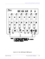
(DMOD) board(s). For a schematic of the Modulator Driver see drawing "SA Series Overall
Schematic." For a diagram of the Modulator Driver, see drawing "SA Series Exciter Control
Motherboard Diagram."
Summary of Contents for SA100
Page 20: ...SOUTHERN AVIONICS COMPANY Model SA100 Dual x Contents...
Page 22: ...SOUTHERN AVIONICS COMPANY Model SA100 Dual 1 2 Introduction This page intentionally left blank...
Page 25: ...SOUTHERN AVIONICS COMPANY Model SA100 Dual 1 5 Introduction Figure 1 2 Transmitter Portrait...
Page 26: ...SOUTHERN AVIONICS COMPANY Model SA100 Dual 1 6 Introduction This page intentionally left blank...
Page 28: ...SOUTHERN AVIONICS COMPANY Model SA100 Dual 1 8 Introduction This page intentionally left blank...
Page 119: ...SOUTHERN AVIONICS COMPANY Model SA100 Dual 3 3 Antennas Figure 3 1 Antenna Reactance...
Page 120: ...SOUTHERN AVIONICS COMPANY Model SA100 Dual 3 4 Antennas This page intentionally left blank...
Page 160: ...SOUTHERN AVIONICS COMPANY Model SA100 Dual 5 8 Maintenance This page intentionally left blank...
Page 162: ...SOUTHERN AVIONICS COMPANY Model SA100 Dual 6 2 Parts List This page intentionally left blank...
Page 164: ...SOUTHERN AVIONICS COMPANY Model SA100 Dual 6 4 Parts List This page intentionally left blank...
Page 218: ...SOUTHERN AVIONICS COMPANY Model SA100 Dual 6 58 Parts List This page intentionally left blank...


