SOUTHERN AVIONICS COMPANY
Model SA100 Dual
2-36
Theory of Operation, Radiobeacon
2.3.10 Monitor
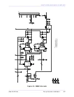
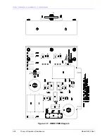
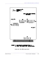
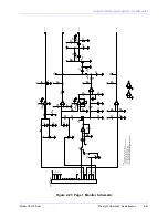
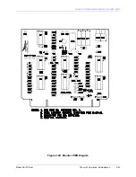
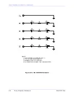
The monitor system consists of three separate boards. The RF out from the filter board is routed
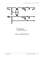
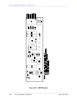
through the HWRF PWB to the transmitter output. Forward and reflected power are sampled by
T1, T2, C1, C2, and R1, rectified, and routed to the MONITOR CTRL PWB and AMTR PWB. A
voltage sample is also taken across R6 for modulation percentage metering.
The forward and reflected power signals on the AMTR1 PWB drive a front panel meter through
calibration resistors. The modulation signal is separated into an average signal and an audio
level signal and used to drive the front panel meter for a modulation percentage reading.
The reflected power signal from the HWRF PWB is applied to pin 7 of comparator U5A on the
MONITOR CTRL PWB and compared with the adjustable voltage applied to pin 6. If the
reflected power signal is greater than the adjusted voltage, pin 1 goes high and sets Latch U2
which applies a high signal to one of the U3A NOR gate inputs. This generates a shutdown
signal at the board shutdown output.
The reset control grounds pin 18 of the MONITOR CTRL PWB which applies a high to the reset
inputs of U4 resetting the outputs of U4 to 0 if the set input is 0.
The forward power signal from the HWRF PWB is applied to R19 on the Monitor Control PWB.
R19 is adjusted for a voltage at pin 5 of U5B less than the voltage at pin 4 at the low power
shutdown level. This forces a 0 at pin 2 of U5B and holds the voltage at TP6 to approximately
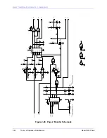
1.0 VDC, which causes a shutdown after a time delay. The voice and keyed code tone signals
are applied to synchronous detector Q5 where the tone is separated out and detected. Q5, turns
on and off synchronously with a reference obtained through U6B from the Tone Key PWB. The
output of Q5 is a DC voltage proportional to the modulating level of the identifying tone. The DC
voltage is compared at U5C pin 9 with a carrier reference level at U5C pin 8. The presence of a
tone modulation percentage higher than that established by R36 is indicated by a high signal on
U5C pin 14. A low-tone level will be indicated by a low signal at U5C pin 14. With the transmitter
operating properly, U5B pin 2 will be approximately 12V and U5C pin 14 will alternate with the
code tone pulses between approximately 12V and 0.5V. TP6 will alternate between 12V and 6V.
The transitions in the TP6 voltages are coupled through C12 to Q2. This turns on Q2 and
prevents C14 from charging. If the RF current or tone modulation percentage drops below the
levels set by R19 and R36 respectively, TP6 will be held at +1.0V or 6V respectively, causing
C14 to charge unijunction transistor Q2 after a nominal 25 second delay. If the tone is on
continuously, TP6 will be held at 12V, C12 will charge, and Q2 will not turn on, with the same end
result. The pulse on R15 sets Latch U4 high which generates a shutdown signal at the board
shutdown output.
If the MONITOR switch is in ENBL, the shutdown signal is applied to the DMOD PWB and the
DC PWB, which turns off the Power Amplifier high voltage. In DSBL, the shutdown input to the
DMOD PWB is grounded, disabling shutdown action. RF OFF is effected by switching 12V on to
the DMOD PWB shutdown line. This is the same as a shutdown signal and turns off the Power
Amplifier high voltage. RF ON removes the 12V and connects the shutdown output from the
MONITOR CTRL PWB to the DMOD PWB and DC PWB shutdown line.
Summary of Contents for SA100
Page 20: ...SOUTHERN AVIONICS COMPANY Model SA100 Dual x Contents...
Page 22: ...SOUTHERN AVIONICS COMPANY Model SA100 Dual 1 2 Introduction This page intentionally left blank...
Page 25: ...SOUTHERN AVIONICS COMPANY Model SA100 Dual 1 5 Introduction Figure 1 2 Transmitter Portrait...
Page 26: ...SOUTHERN AVIONICS COMPANY Model SA100 Dual 1 6 Introduction This page intentionally left blank...
Page 28: ...SOUTHERN AVIONICS COMPANY Model SA100 Dual 1 8 Introduction This page intentionally left blank...
Page 119: ...SOUTHERN AVIONICS COMPANY Model SA100 Dual 3 3 Antennas Figure 3 1 Antenna Reactance...
Page 120: ...SOUTHERN AVIONICS COMPANY Model SA100 Dual 3 4 Antennas This page intentionally left blank...
Page 160: ...SOUTHERN AVIONICS COMPANY Model SA100 Dual 5 8 Maintenance This page intentionally left blank...
Page 162: ...SOUTHERN AVIONICS COMPANY Model SA100 Dual 6 2 Parts List This page intentionally left blank...
Page 164: ...SOUTHERN AVIONICS COMPANY Model SA100 Dual 6 4 Parts List This page intentionally left blank...
Page 218: ...SOUTHERN AVIONICS COMPANY Model SA100 Dual 6 58 Parts List This page intentionally left blank...

