


SOUTHERN AVIONICS COMPANY
Model SA100 Dual
2-46
Theory of Operation, Radiobeacon
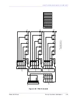
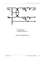
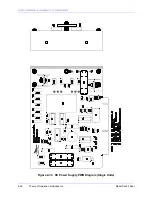
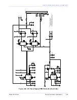
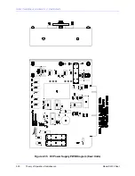
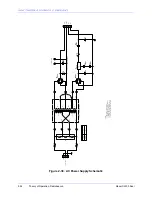
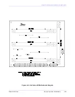
2.3.11 DC Power Supply (Optional)
The DC PWB consists of a step-up switching regulator that converts the 24V battery voltage to
the high voltage needed by the Modulator, and a step-down switching regulator that supplies 12V
to the various low level circuits.
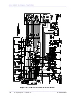
U1 is a regulating pulse width modulator circuit with inputs at pins 1 and 2 and outputs at pins 11
and 14. Output pulse width is proportional to the differential voltage between pins 1, and 2.
Feedback voltage is applied at pin 1 and pin 2 voltage is adjusted with R2 for 175V at the High
Voltage output. This DC voltage is slightly less than the DC voltage supplied by the AC Power
Supply when the input AC is at its lowest "in specification" level. This means that there is
normally a slight reduction in output power when AC Power is lost and the batteries supply
power. Frequency is determined by R6 and C3 and is approximately 100 KHz. U2 and U3 drive
FET's Q1 and Q2. The shutdown signal from the MONITOR CTRL PWB turns the high voltage
off by applying 12V to pin 11 of U2 and U3. U4 controls the pulses for the 24 to 12V stepdown
switching regulator. R17 adjusts the feedback voltage so that the low voltage output to the
Exciter and the other low level circuit is 12V.
For Single Units:
Low battery voltage disconnect is effected by U5B. When the voltage drops to an adjusted value,
the output of U5B goes high, and opens relay K1, which shuts down the transmitter.
For Dual units or units with output power greater than 100 watts:
Refer to the DC Auto Disconnect section for low battery voltage cut out.
Summary of Contents for SA100
Page 20: ...SOUTHERN AVIONICS COMPANY Model SA100 Dual x Contents...
Page 22: ...SOUTHERN AVIONICS COMPANY Model SA100 Dual 1 2 Introduction This page intentionally left blank...
Page 25: ...SOUTHERN AVIONICS COMPANY Model SA100 Dual 1 5 Introduction Figure 1 2 Transmitter Portrait...
Page 26: ...SOUTHERN AVIONICS COMPANY Model SA100 Dual 1 6 Introduction This page intentionally left blank...
Page 28: ...SOUTHERN AVIONICS COMPANY Model SA100 Dual 1 8 Introduction This page intentionally left blank...
Page 119: ...SOUTHERN AVIONICS COMPANY Model SA100 Dual 3 3 Antennas Figure 3 1 Antenna Reactance...
Page 120: ...SOUTHERN AVIONICS COMPANY Model SA100 Dual 3 4 Antennas This page intentionally left blank...
Page 160: ...SOUTHERN AVIONICS COMPANY Model SA100 Dual 5 8 Maintenance This page intentionally left blank...
Page 162: ...SOUTHERN AVIONICS COMPANY Model SA100 Dual 6 2 Parts List This page intentionally left blank...
Page 164: ...SOUTHERN AVIONICS COMPANY Model SA100 Dual 6 4 Parts List This page intentionally left blank...
Page 218: ...SOUTHERN AVIONICS COMPANY Model SA100 Dual 6 58 Parts List This page intentionally left blank...