background image

Summary of Contents for SS-800AVS

Page 1: ...NUFACTURERS OF LOW FREOUENCY RADIOBEACONS AND ASSOCIATED PRODUCTS MODEL SS 800AVS NON DIRECTIONAL RADIOBEACON MANUAL 80AVS 90 2 BOX 5345 BEAUMONT TEXAS 77726 5345 USA TELEPHONE 409 842 1717 CABLF SAC...

Page 2: ...h the warranty COMPANY will repair or replace F O B point of manufacture any such goods but in no event will COMPANY be obligated or required to remove the non conforming goods from their place of ins...

Page 3: ...y 41 2 2 8 Battery System 45 2 2 9 AM Auto Shutdown PWB 49 2 2 10 Power Switch PWB Assembly 53 2 2 11 Metering Circuit 57 2 2 12 Reset SSC PWB 61 3 THEORY OF OPERATION ANTENNA COUPLER 69 3 1 FUNCTIONA...

Page 4: ...Specific Precautions 109 6 1 3 Test Equipment List 109 6 1 3 1 Field Service or Checkout ii0 6 1 3 2 System Alignment and Calibration ii0 6 2 System Alignment and Calibration iii 6 2 1 AM Oscillator P...

Page 5: ...ndby Assembly 47 AM Auto Shutdown PWB Schematic 50 AM Auto Shutdown PWB Assembly 51 Power Switch PWB Schematic 54 Power Switch PWB Assembly 55 Meter PWB Schematic 58 Meter PWB Assembly 59 Meter Bracke...

Page 6: ...Symmetrical T Antenna and PC 1000 93 Synthesizer Bands 97 Control and Testpoin Positions 98 iv Southern Avionics SS 800AVS Company...

Page 7: ...perates on 115 230 VAC 50 60 Hz or 48 VDC An automatic shutdown circuit is included that automatically shuts down the transmitter if power falls below an adjustable level if the ident signal fails or...

Page 8: ...78 7 5 BOTTOM VIEW CONDUIT ENTRANCE LOCATIONS NOTES I IN OUT CONNECTIONS ARE MAOE WITH FLEXIBLE CONI JI THROUGH THE BOTTOM 2 THIS DRAWING NO 1471 REV B 3 DIMENSIONS IN INCHES CM 4l NET wT 4SLBS 2OKGL...

Page 9: ...Hz or 1020 Hz tone International Morse Code any combination of up to three letters or numerals and or optional voice modulation Modulation percentage adjustable from 0 i00 percent Code modulation per...

Page 10: ...tivity AGC stage will accept input levels of 28 dBm to 5 dBm without modulation percent change Attack and decay times adjusted for voice type line signals Over Modulation Control Limits modulation of...

Page 11: ...the circuit i Line impedance 600 ohms balanced audio only 2 Line equalization for frequencies 400 Hz to 2800 Hz 3 Maximum line input 5 dBm 4 Normal equipment input 8 dBm 5 Maximum line loss 12 dBm If...

Page 12: ...is controlled by the Autotune Motor Drive PWB in the coupler The coupler is mounted in a metal enclosure with dimensions 22 5 57 cm wide 21 5 55 cm deep 26 5 67 cm high and is designed for outdoor mo...

Page 13: ...DE WITH FLEXIBLE CONDUIT THROUGH THE BOTTOM 2 THIS DWG NO 2_716 3 DIMENSIONS IN INCHES CM 4 NET WT 46 LBS I KS 5 MOUNTING CENTER LINE 11 5 CENTERS DERCTED TOWER LEG MOUNT 11 25 CENTERS COUPLER ENCLOSU...

Page 14: ...mperature 50 C to 70 C relative humidity 0 to 100 high salinity as encountered in offshore con ditions The antenna coupler is designed for outdoor mounting at the base of the antenna POWER REQUIREMENT...

Page 15: ...tion during voice signal presence The modulated RF signal is filtered and then fed to a linear amplifier consisting of a Class A preamplifier a push pull class AB driver stage and a parallel push pull...

Page 16: ...UNIT I UNIT OPT ONAL AU0 L TT R PW8 NOT I THIS DRAWING NO 4401...

Page 17: ...ers and amplifies the output of the Q1 oscillator to drive the RF output and the phase lock logic circuits The output of buffer Q2 is fed to programmable divider U3 where the oscillator frequency is d...

Page 18: ...120 RF PWB 129 PROGRAMMING COMPONENTS F kHz C1 C C3 C4 C5 LI 190 250 O00pF O00pF O00pF 500pF 65 1 3mH 40 34 0 2000pF 2000pF O00pF 500pF 280 650 H 320 415 2000pF 300pF 415 6 0 O00pF OO0 eO0 lO00pF 30O...

Page 19: ...oJI o 1 0 MHz 0 5 K Hz U3 OFF S4 1UI x I00 kHz I NOTE5 I THIS ORAWING NO G3t R A TI 3 Ltr D SYI ITHr 1ZER PWI 2 SCH ATIC DRAWING 4 3 PARY NO PWB SYNTHESIZER PWB ASSEMBLY SS 800AVS Southern Avionics Co...

Page 20: ...0 0 0 o 0 0 NOTES L REE DES PREFIX AIAISAI 2 PART NO PWB 17 9 653 3 THIS DRAWING NO 653 REV 4 SEE BOM SYNTHESIZER PROGRAMMING PWB ASSEMBLY 16 Southern Avionics Company SS 800AVS...

Page 21: ...rnished through the Driver PWB from the Auto Shutdown PWB The audio input signals to the AM Oscillator PWB are derived from the AM Recycle PWB and or from the optional Audio PWB The audio signals are...

Page 22: ...AM OSCILLATOR PWB SCHEMATIC 18 Southern Avionics Company SS 800AVS...

Page 23: ...953 REV B TITLED AM OSCILLATOR PW8 59 2955 2 SCHEMATIC DRAWING NO 13 5 PART NO PWB 59 2 95 5 4 REF DES PREFIX IAI 5 SEE BOM Z95 REV 8 6 Cl ND RI NOT USED AM OSCILLATOR PWB ASSEMBLY SS 800AVS Southern...

Page 24: ...f U2A The resistance is controlled by the signal level fed back from pin 1 of U2A As the signal level increases the gate voltage on decreases and the resistance decreases thus lowering the audio input...

Page 25: ...AUDIO PWB SCHEMATIC 22 Southern Avionics Company SS 800AVS...

Page 26: ...RAWING NO 20 3 REV B Z SCHEMATIC DWG 2062 REV B 3 REF DES PREFIX A3A9 SS KILO AIAI3 SSK 4 PART NO PWB 214 2063 5 BOM 2063 REV B 6 TITLE AUDIO PWB 214 2063 ASSEMBLY AUDIO PWB ASSEMBLY SS 800AVS Souther...

Page 27: ...dot or dash depending on its R C time constant For example consider the letter D _ There are only three characters so the first one shot is not used A jumper is placed at J3 to couple the input trigg...

Page 28: ...schematic starting with the jumpered stage Dashes will be generated automatically and any dash may be changed to a dot by adding a 220K ohm resistor in parallel as shown in dotted lines Also if Jl is...

Page 29: ...d circuit U2 Quad Transmission Gate Integrated circuit Ul Operational Amplifier and its associated circuitry function as an audio oscillator to provide an identifi cation tone 1020 Hz or 400 Hz to pin...

Page 30: ...MORSE CODE Letters So T U V W X y Z Numbers 8 9 0 28 Southern Avionics Company SS 800AVS...

Page 31: ...LETTER PWB SCHEMATIC SS 800AVS Southern Avionics Company 29...

Page 32: ...LETTER PWB ASSEMBLY 30 Southern Avionics Company SS 800AVS...

Page 33: ...SA O08 SS...

Page 34: ...NUMBER PWB ASSEMBLY 32 Southern Avionics Company SS 800AVS...

Page 35: ...Xu d oo so uo A ua q nos SA 008 SS DI Z HDS flMd qD D H kT T...

Page 36: ...0 D D I 0o o o...

Page 37: ...4 TP4 blue is used to monitor the signal from the preamp and the DC voltage on the preamp This voltage is controlled by the automatic shutdown circuit Test point 2 TP2 red is used to monitor the drive...

Page 38: ...BLACK CRI IN4004 R3 4 7 CI 1 0 Ii iI NOTES I THIS DRAWING NO 4181 REV B 2 TITLE DRIVER PWB SCEMATIC 3 ASSEMBLY DRAWING NO 4109 4 REF DES PREFIX IA7 5 ALL RESISTORS II2V fOX UNLESS NOTED 6 ALL CAPACITO...

Page 39: ...XOl 1 NOTE 1 THIS DRAWING NO 4109 REV A 2 TITLE DRIVER PWB ASSEMBLY 5 SCHEMATIC DRAWING NO 4121 4 PART NO PWB 222 4109 5 REF DES PREFIX 1A7 DRIVER PWB ASSEMBLY SS 800AVS Southern Avionics Company 37...

Page 40: ...he factory with a specific range of current gain CR4 CR5 CR7 CR8 R5 R9 RI5 and RI9 provide protection when an inductive load or open circuit causes large voltage spikes at the transistor collectors T2...

Page 41: ...4 1 0 Iw INSSSSA a t 190 340 kH 340 500 kHz CS e 0 01 O0068 o oo LI IBT i T II T I AUTO m I SHUTDOWN I PW8 L J TB4 eNC I I METER PW I I O0 0 0 NOTES I THIS DRAWING NO 660 REV H TITLEO S OOA FINAL STAG...

Page 42: ...red 50 VDC supply At normal loading of about 6 amps the peak to peak ripple will be approximately one volt The 14 volt regulated supply for the Keyer AM Oscillator PWB Audio PWB and Auto Shutdown PWB...

Page 43: ...SURGE VOLTAGE u JI E PROTE R NOTES I REFERENCE DESIGNATION PREFIX I 2 CAPACITOR VALUES IN MICROFARADS 3 IF RATTERY STANDBY IS NOT USED USE PLUG XP3 WITH PINS 3 AND 5 JUMPERED 4 SEE 50 VOLT POWER SUPP...

Page 44: ...SA O09 SS...

Page 45: ...volts by T1 and CRI CR4 Charging current is regulated at approximately 2 amps maximum with current sensed across R7 and R8 and current level controlled with QI Q2 and Q3 Ul RI7 and CRI0 latch the char...

Page 46: ......

Page 47: ...I REF D S PREFIX AI2 4 SEE PANTS LIST 265S P O SOM 962 ROTES I THIS DRAWI v6 NO 954 R O TITLEO SSC ATTERY REGULATOR PW8 S MATi GNAWING NO 4 FART NO PWB 6 SEE BOM 964 SEE WIN iST 7 R7 8 i2 i4 29 S U D...

Page 48: ...is a DC voltage proportional to the modulating level of the iden tifying tone The DC level from U2 pin 2 is compared at UlC pin i0 with a carrier reference level at UIC pin 9 The presence of a tone m...

Page 49: ...TPI BLU 120K I OOFF 1 05 TO I 90T TOM VI W...

Page 50: ...I THIS ORAWING NO 2329 REV D TITLED AM AUTO SHUTDOWN PWB 221 2329 2 SCHEMATIC DRAWING NO 2328 3 REF DES PREFIX 4 PART NO 221 2329 5 BOM 2329 AM AUTO SHUTDOWN PWB ASSEMBLY SS 800AVS Southern Avionics C...

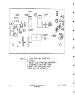
Page 51: ...LED on the assembly will light indicating that power is being removed from the final transistors Overall high current conditions are sensed by QI If current through RI R2 exceeds approximately 25 Amps...

Page 52: ...I 30 0 0 P O PI 4iV Z O T SWITCHED OUTPUT pOWER VG MCR O 3 US R 31...

Page 53: ...THIS DRAWING NO 1477 REV D 4 STAND OFF R18 21 22 I 4 OFF PWB 5 Q4 Q5 ARE LOCATED ON BRACKET SHT 2 6 SCHEMATIC DRAWING NO 1476 7 C2 5 CR8 11 RlO 13 Nor USED B STAND OFF R1 2 3 4 OFF PWB g BOM 1411 POWE...

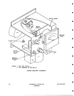
Page 54: ...t transformer in the output circuit The emitter volts measurement is a DC voltage measurement across one of the one ohm emitter resistors and thus gives a direct measurement of DC current in the final...

Page 55: ...INAL 0 TRANSISTOR RIS 2BK l II W PROOF JACK O 1 RI4 2 51 RI 2 I o o NOT B I THIS DRAWING NO 141 2 R V Ao TITLEDi METER PW IZ3 14 3 SCHEMATIC 2 ASSEMBLY DRAWING NO 14T3 3 REF 0E PREFIX All 4 ALL RESIST...

Page 56: ...T NOT ES I THIS DRAWINg NO 1473 TITLED METER PW8 123 1473 2 SCHEMATIC DRAWING NO 1472 REV A 3 REF OES PREFIX All 4 PART NO PWB 17 3 1473 5 SI MOUNTED ON OTHER BIDE G R3 NOT USED 7 SEE BOM 1473 REV A B...

Page 57: ...METER SWITCH AItSI CIRCUIT OREAKER PROBE JACK J2 cs I OTE e REF DES PREFIX I 2 THIS ORAWlNG NO SSO REV B METER BRACKET ASSEMBLY METER BOARO All USE FI AIIMI 60 Southern Avionics Company SS 800AVS...

Page 58: ...to approximately one volt This negative going signal passes through C1 on the Reset SSC PWB to UIA on the Reset SSC PWB UIA and UlB form a set reset flip flop which is normally in an initial reset sta...

Page 59: ...ount up to the next reset operation at approximately one hour Pressing the manual pushbutton Sl located on the Reset SSC PWB will cause both the reset circuits and the Autoshutdown PWB to be returned...

Page 60: ...CR6 I OOK N400 Y Z A r Q2 Ul I k VV 2N3711 R14 I i 1OK 9 2 K NOTES 1 THIS DWG NO 3308 R A 2 LE AUTOSHUTDOWN RESET PWB 246 3309 SCHEMATIC 3 L RESISTORS 1 4W lO UN SS NOTED 4 L PACITORS IN F UN SS NOTED...

Page 61: ...UI NOTES 1 THIS DWG NO 3309 REV 2 TITLEi RESET SSC PWB 246 ASSEMBLY 3 SCHEMATIC DVG NO 3308 4 PART NO P B 24G 3309 RESET SSC PWB ASSEMBLY 64 Southern Avionics Company SS 800AVS...

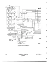
Page 62: ...STANDOY AI2 1 TRANSMITTER SCHEMATIC SS 800 66 Southern Avionics Company SS 800AVS...

Page 63: ...FINAL AMPLIFIER I IP 4004 INSGSSl G3 1 0 F4 I TUNING INPUT FIGURE 2 26 SS BOOAV TRANSMITTER SCHEMATIC TRANSMITTER SCHEMATIC CONT SS 800AVS Southern Avionics Company 67...

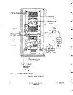
Page 64: ...MITER SWITCH II O3 qNC OUTPUT REHINO OUTPUT F I t T IF R CAPACITOR t THIS DRAWING NO 2t74 RF_ V C TRANSMITTER DIAGRAM RF 0RIVE CONTROL 68 Southern Avionics Company SS 800AVS...

Page 65: ...tatable shorted turn for fine adjustment Tuning range is from 22 uH to 3 6 mH which is sufficient to tune any practical antenna in the 190 625 KHz frequency range 3 1 3 Autotune The autotune circuit c...

Page 66: ...N L TO TRANSMITTERS 0 0 _ RF IN AUTOTUNE 14V ANTENNA CURRENT TUNING METER VSWR SAMPLE CURRENT SAMPLE XFMR IMPEDANCE XFMR TUNER mmmm TO ANTENNA NOTES I THIS DRAWING NO IO28 REV A TITLED PC BLOCK DIAGR...

Page 67: ...de with a solder connection behind a removable panel The lower tap selection is made with a switch on the front panel The autotune system automatically turns the tuning ring in a direction to tune the...

Page 68: ...0...

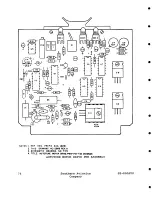
Page 69: ...he current and voltage signals and feed them into U3 for deter mination of the magnitude of the phase difference between the current and voltage signals The output of U3 pin ii is filtered by RI2 and...

Page 70: ...l be activated with 14 V at U7 pin i0 and 0 V at U7 pin 6 DS2 will light and the motor will rotate to decrease the inductance of coupler transformer T3 Rotation will continue until the logic signals a...

Page 71: ...u dmoD SO UO A ua q nos SA 008 SS...

Page 72: ...TES I REE DES PREFIX 2A2 1A AI 2 THIS DRAWING NO Z909 REV A SCHEMATIC DRAWING N0 74 4 TITLE AUTOTUNE MOTOR DRIVE P fB 142 7 DIAGRam AUTOTUNE MOTOR DRIVE PWB ASSEMBLY 76 Southern Avionics Company SS 80...

Page 73: ...by Q2 The detected signal is calibrated with RI0 and RII and fed to the 1 mA meter An RF signal proportional to reflected power is generated by T4 and C2 in the antenna coupler and fed to Q3 on the A...

Page 74: ...R PWB NOTES I REE DES PREFIX 2AL 2 THIS ORAWING NO 64G REV G SS IdALY OR W NG NO G41 ALL RE 1STONS 114 W UNLESS NOTEO ALL CAPACITORS IN MFO UNLESS NOTEO RI3 NOT USi O ON PColOOO Tt NIN0 INOICATION OUT...

Page 75: ...083 REV B TITLED ANTENNA CURRENT TUNING METER PWB 118 641 2 SCHEMATIC DRAWING NO 646 REV G 3 PART NO PWB 118 641 4 REF OES PREFIX gAl 5 SEE PARTS LIST 2083 ANTENNA CURRENT TUNING METER PWB ASSEMBLY SS...

Page 76: ...ance may be as high as 50 ohms and the antenna efficiency will be very low THE MAST ANTENNA H ANTENNA AND 50 FOOT GUYED MAST ANTENNA ARE HIGH Q NARROW BANDWIDTH ANTENNAS THEY SHOULD NOT BE USED FOR VO...

Page 77: ...pF capacitor in series with a small resistor See the figure at the end of this section for a plot of the capacitive reactance 4 2 H Antenna The H Antenna is used on the helipad of offshore structures...

Page 78: ...itter for most locations in the United States and with one of the lower priced ADF s is from 80 to i00 miles except over low conductivity ground These range figures are for the standard T Antenna with...

Page 79: ...NOTE o0o 25O0 2000 1500 I000 500 ZOO 250 300 350 THIS DWCt NO 1031 ANTENNA REACTANCE 84 Southern Avionics Company SS 800AVS...

Page 80: ...bly and the Transmitter Schematic and Diagram in section 2 DO NOT APPLY POWER AT THIS TIME Connect the jumper on each transmitter TB4 from terminal 1 to terminal 3 o Check that the straps on the power...

Page 81: ...sulator bushing Dress all leads at least 2 inches from metal surfaces Locate and install the lightning arrestor with the two screws located between the insulator bushing and the front access door Adju...

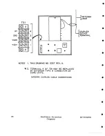
Page 82: ...3 ANTENNA LEAD OUPLER UTPUT TERMINAL NOTES I THIS DRAWING NO 32 7 REV A t 2 TERMINAL 4 OF TBI MAY BE REPLACED BY EXTERIOR TYPE N CONNECTOR ON SOME UNITS ANTENNA COUPLER CABLE CONNECTIONS 88 Southern...

Page 83: ...f kHz 190 220 220 250 250 290 290 625 MAST ANTENNA 9 8 7 6 50 FOOT GUYED MAST 7 7 6 6 5 4 4 4 NOTES I THIS DRAWING NO 107_2 IMPEDANCE TRANSFORMER TAPS SS 800AVS Southern Avionics Company 89...

Page 84: ...MPLF 2 O I Hz CAN 8 TUNED WITH OOARSE TAP I O AND FINE TAPS IS AND 20 OR COARSE TAP I00 AND FINE TAP 40 USE A TAP COMBINATION THAT PLACES THE FtNE TUNING RING NEAR ITS MIDPOINT 40O NOTE I THIS DRAWING...

Page 85: ...ILL INTER SECT ALL USABLE TAP COMSINATIONS FOR EXAMPLE 4 0 Hz CAN BE TUNED WITH COARSE rAP 40 ANO FINE TAPS 0 24 AND 28 OR COARSE TAP ZO AND FINE TAP 40 USE A TAP T ING RING NEAR ITS MIOPOINT MAST ANT...

Page 86: ...H AN BE TUNED WITH COARSE TAP I00 AND FiNE TAPS 12 AND 1S OR COARSE TAP BO AND FINE TAPS 36 AHO 40 USE A TAP COMBINATION THAT PLACES THF FINE TUNING RING NEAR ITS MIDPOINT 300 350 400 f KHz 450 OCTOBE...

Page 87: ...CAN BE TUNED WITH COARSE TAP 40 ANO FINE TAPS I AHO ZO OR COARSE TAP 20 AND INS TAPS AT SG ANO 40 USE A TAP COMGINATION THAT PLACFS THE F1NE TUNING R1Ng NEAR ITS MIDPOCHT 3S0 4 00 I KH t450 SO0 SSO I...

Page 88: ...on the AM Oscillator PWB is fully CCW Connect the jumper on TB4 from Terminal 1 to Terminal 2 5 Apply power to the transmitter Note the voltmeter reading If the voltmeter reads 0 the LC oscillator is...

Page 89: ...perature of 77 F 25 C Readjustment of the error voltage to 5 0 volts after arrival of the transmitter at the final ambient temperature is recommended to allow the greatest tolerance to temperature and...

Page 90: ...00 1800 KHz FILTER 190 340 KHz 340 500 KIIz 190 250 Kllz 250 340 340 500 Kllz 500 625 Kllz 500 625 1500 1800 KHz SYNT ES IZ ER PROGRAMMING BOARD PWB 129 NOTE I 190 250 Kllz 240 340 KHz 320 415 415 625...

Page 91: ...IUST TPZ RI2 MOO LIMIT R39 RF ORIVE OSC R6 lUOlO INPUT LEVEL AUDIO INPUT AUDIO PWB TP2 ASB TEST SI AUTO SHUTDOWN PW8 RS SHUTDOWN OFF_ON__ LEVEL 20 R4 4 MOO LIMIT MOO ADJUST DRIVER PWB NOTE TP4 TP5 OU...

Page 92: ...tton Slowly turn the RF DRIVE control CW DO NOT allow the EMITTER VOLTS to go above 0 5 DO NOT allow the TUNE indication to go above half scale The TUNE indication may momentarily increase if the auto...

Page 93: ...he reading Turn RF DRIVE fully CCW Increase the IMPEDANCE TRANSFORMER tap in the antenna coupler by one number and adjust RF DRIVE to i00 watts Check the relative TUNE indication on the meter If it is...

Page 94: ...corona discharge and solder the wire to the selected coil coarse tap Install the coil enclosure cover above the coupler control panel SS 800AVS Southern Avionics Company i01...

Page 95: ...de Continuous high level code no voice Continous high level voice with continous low level code in background High level voice with low level code in background while voice signal present on audio lin...

Page 96: ...ved from the AM Recycle PWB 5 6 Tone Modulation Adjustment Tone modulation percentage is factory set using the procedure under the Frequency and Percent Modulation Adjustment in section 6 To check mod...

Page 97: ...inputs 15 dBm to 7 dBm set to C2 position b For low level audio line inputs 28 dBm to 15 dBm set to Cl position c Set switch 2 on the Audio PWB to ON to activate the audio AGC do Check that R6 on the...

Page 98: ...ter function switch in the 25 DC volts position and connect the test probe furnished with the transmitter between the Probe Jack terminal next to the meter and TP2 on the Autoshutdown PWB See figure C...

Page 99: ...VE for full power The Automatic Shutdown System will also shut down the transmitter if extreme distortion is present 5 7 4 Final Check that S1 on the Recycle PWB is in IDENT and that the ON OFF switch...

Page 100: ...ns when working with components mounted on a PWB Insufficient care or excessive heat in soldering and desoldering can lift component pads thus destroying a PWB Use a Solder Wick or equivalent when des...

Page 101: ...dard electronics type hand tools 4 Low wattage soldering iron 25W with chisel tip 5 Plastic alignment tools GC8606 and GC8275 6 1 3 2 System Alignment and Calibration i All of the aforementioned equip...

Page 102: ...2 Turn the RF DRIVE control on the AM Oscillator PWB to its full low level CCW position 3 Put Switch Sl on the Recycle PWB in the continuous carrier positionn CARR 4 Set the Auto Shutdown PWB switch t...

Page 103: ...io level using the audio oscillator control and or R6 on the Audio PWB for 1 VRMs at TP1 of the Audio PWB 3 Rotate Modulation Limit Control R44 located on the Audio PWB fully CW to defeat the limiter...

Page 104: ...ad Calcium 24 cells 2 17 to 2 25 volts cell 52 1 to 54 0 volts Nickel Cadmium 38 cells 1 40 volts cell 53 2 volts As required adjustment may be made to these values instead of 52 4 volts Disconnect AC...

Page 105: ...E In a fully charged battery the terminal voltage may drop very slowly to the normal float voltage If no change is noted as R22 is rotated the system is not stabilized Allow more time and again try ad...

Page 106: ...s 3 With continued exposure to an extreme environment the fiberglass parts of the antenna system may need to be cleaned and sealed This is especially true in a salt water or high soot environment whic...

Page 107: ...ANTENNA RESISTANCE DATE EMITTER DC VOLT AGE ON FINALS RF TOP TOP BTM BTM CUR LFT RGT LFT RGT PWR LOADING SWITCH POSN PERSON MAKING CHECKS FCC SGN LIC REMARKS 116 Southern Avionics Company SS 800AVS...

Page 108: ...iobeacon to quickly gain familiarity with the normal voltages and waveforms associated with an SS Series transmitter In addition whenever possible an attempt has been made to list some of the abnormal...

Page 109: ...PWB in CONT Shutdown switch OFF rated power into dummy load or antenna Full INDICATION REMARKS ACTION Waveforms DC Voltages 12 to 14 5 V Normal 100 modu I lation Peak to peak voltages will vary accord...

Page 110: ...ll INDICATION REMARKS ACTION DC Voltages Normal 48 to 55 V 0 V Wave forms No output from 50 V power supply Normal Peak to Peak voltages will vary according to drive requirements of individual transmit...

Page 111: ...icates saturation of driver transistors due to excessive drive level de tuned antenna system open in driver output transformer etc Check for over driving waveform becomes clean when drive is reduced i...

Page 112: ...0 6 V 0 2 V 0 V 5O V Waveforms Bais diodes to final shorted Fuse to final blown Final bias diodes open Final emitterl resistors open Final transistors ishorted or open Normal Peak to peak voltage may...

Page 113: ...Driver tran sistors open or shorted Normal Peak volt ages may vary according to individual transmit ters CIRCUIT Final Amplifier Emitter Current TEST POINT Each final emitter resistor MODE S1 on Recyc...

Page 114: ...tely three times VDC CIRCUIT Final Amplifier Collector Voltage TEST POINT Each final collector case MODE Sl on Recycle PWB in CONT Shutdown switch OFF rated power into dummy load or antenna Full INDIC...

Page 115: ...n Q2 through Q5 etc R6 Auto Shutdown PWB level adjustment alignment improper Check transmitter output for keying Perform resistance voltage measurements on circuit concerned CIRCUIT Auto Shutdown PWB...

Page 116: ...nly after 15 to 60 second delay CIRCUIT Auto Shutdown PWB 14 V regulated supply TEST POINT TPI blue on Auto Shutdown PWB MODE AC power applied or 48 VDC applied if operating from batteries INDICATION...

Page 117: ...S DC Voltages Normal 0 V Electronic Keyer Recycle and Letter PWB Pin 17 Recycle PWB AC power applied Sl on Recycle PWB in CONT ACTION CIRCUIT Electronic Keyer Recycle and Letter PWB TEST POINT Pin 17...

Page 118: ...by assembly It is important that the entire reference designator and the part description be used when ordering parts The serial number of the unit should also be included in any parts order SS 800AVS...

Page 119: ...AME AS CRI DIODE SILICON DIODE TRANZSORB SILICON SAME AS CR4 SAME AS CR3 SAME AS CR4 PART NO SS 800AVS FAH 6500 75 BE MMW 2WI 27110BI03J00 DMI9 682J 27120B402J00 44 I00 PI0 INI203R IN4004 IN5658A CR8...

Page 120: ...ASE SPECIFY BETA DESIRED WHEN ORDERING 2384 2383 2382 72 T SSCP K 5146 K 1443 PWRSWSUPPLUGSSC SSCBATTSBYRECP PWRSWEMTRPLUG80 2N567288 R1 RES 300 OHM 5W 10 WW 4604 R2 RES 27 OHM I 2W 10 CC OE2701 R3 NO...

Page 121: ...T1 T2 T3 TBI TB2 TB3 TB4 TB5 A1 AM OSCILLATOR PWB ASSY IPWB 59 2953 BAND A2 AM RECYCLE PWB ASSY PWB 60 3002 A3 LETTER PWB ASSY PWB 28 189 LETTER OR NUMBER PWB ASSY PWB 40 297 NUMBER A4 SAME AS IA3 A5...

Page 122: ...AI4 NOT USED AI5 SYNTHESIZER PWB ASSY PWB 128 652 PWB 128 653 BAND AI6 RESET SSC PWB ASSEMBLY PWB 246 3309 2 ANTENNA COUPLER PC 1000B 132 Southern Avionics Company SS 800AVS...

Page 123: ...CRIPTION CAP 6 8NF 25V TANT CAP I F 80V FLM CAP 047 F 80V FLM CAP 6 8 F 25V TANT CAP 01 F 80V FLM CAP 220pF 500V DSM CAP 47 F 35V TANT CAP 6 8 F 25V TANT CAP 8 60pF TRMR CAP 6 8 F 25V TANT CAP I F 35V...

Page 124: ...ES 3 3K 25W 10 CC RES IK 25W 10 CC RES 33K 25W 10 CC RES 2 2K 25W 10 CC RES 100K 25W 10 CC RES 10K 25W 10 CC RES 47 OHM 25W 10 CC RES 3 3K 25W 10 CC RES 33K 25W 10 CC RES 6 8K 25W 10 CC RES 2 7K 25W 1...

Page 125: ...DMI9 202J 9055 BAND i 190 240 KHz DESCRIPTION CAP 0033 80V FLM CAP 0056 F 80V FLM INDCTR 120 280 H VAR BAND 2 240 320 KHz DESCRIPTION CAP 0022 F 80V FLM CAP 0033 F 80V FLM INDCTR 120 280 H VAR BAND 3...

Page 126: ...MBER DMI5 471J DMI5 681J 9055 BAND 5 1500 1800 KHz DESCRIPTION CAP 220pF 500V DSM CAP 500pF 500V DSM INDCTR 28 60 H VAR BAND 6 625 1000 KHz DESCRIPTION CAP 680pF 500V DSM CAP 1000pF 500V DSM INDCTR 60...

Page 127: ...V TANT CAP I F 35V TANT CAP I F 35V TANT CAP 6 8 F 25V TANT CAP 01 F 80V FLM CAP 01 F 80V FLM CAP 68 F 15V TANT CAP 01 F 100V CER CAP 01 F 80V FLM CAP 01 F 80V FLM DIO SWITCH 80V 040A LAMP 14 MA i0 V...

Page 128: ...R25 R26 S1 U1 U2 OCI031 0C4731 SF6TBX392 LM307N CD4066BE RES 10K 25W 10 CC RES 47K 25W 10 CC SWITCH 3 POS PC MOUNT T8206 IC OP AMP LM307N IC QUAD BI 138 Southern Avionics Company SS 800AVS...

Page 129: ...D OEI051 OEI031 NOT USED OEI031 OEI041 CAP I F 250V POLY DIODE SWITCH 80V 040A XSTR NPN 30V 03A RES 220K 5W 10 CC RES 470K 5W 10 CC RES 27K 5W 10 CC RES 220K 5W 10 CC RES 10K 5W 10 CC RES 27K 5W 10 CC...

Page 130: ...0V FLM CAP I F 250V POLY CAP I F 50V FLM CAP 6 8 F 25V TANT DIODE ZENER 13V IW DIODE RECT 400V IA DIODE SWITCH 80V 040A DIODE RECT 400V IA SCR 8 AMP 200V XSTR NPN 30V 03A XSTR PNP 25V 2A RES 2 7K 5W 1...

Page 131: ...DWG 2523 DWG 2535 325 103 325 102 325 107 325 105 6072 B HIX 3 4 0 CAP INF 250V POLY DIODE RECT 400V IA XSTR NPN 120V 4AMP RES 4 7K IW 10 CC RES 4 7 OHM 5W 10 CC RES 4 7K IW 10 CC RES 68 OHM IW 10 CC...

Page 132: ...1 F 100V CER CAP I F 35V TANT CAP I F 35V TANT CAP 6 8 F 25V TANT CAP 100 F 25V ELCTLT CAP 33 F 25V TANT CAP I F 35V TANT DIODE ZENER 13V IW DIODE SWITCH 80V 040A RELAY 12VDC SPST XSTR NPN 45V IA XSTR...

Page 133: ...5 105 325 107 LM324N CD4066BE I136B 77175N 477175N SWITCH 2 POS PC MOUNT T820 TESTPOINT BLUE TESTPOINT YELLOW IC QUAD OP AMP IC QUAD BILATERAL SWITCH HTSK TO5 CASE BLACK SQUARE INS PAD XSTR INS PAD XS...

Page 134: ...9 235 CAP I F 35V TANT CAP 001 F IKV CER CAP 6 8 F 25V TANT CAP 33 F 25V TANT CAP I F 35V TANT DIODE ZENER 5 1V IW DIODE RECT 400V IA DIODE RECT 400V IA DIODE LIGHT EMITTING RED XSTR PNP 200V IA XSTR...

Page 135: ...XQI 2 XQ3 5 XQ6 XQ7 8 77175N NOT USED 2228 B 77175N INS PAD XSTR HTSK TO 5 CASE ROUND BLACK INS PAD XSTR SS 800AVS Southern Avionics Company 145...

Page 136: ...3006P I 502 S1 12 RCB6 J PC T1 DWG 440 CAP 01 F 100V CER CAP 22 F 80V FLM XSTR NPN 30V 03A RES 1 2 OHM 5W 10 CC RES 82K 25W 10 CC RES 10K 25W 10 CC RES 4 7K 25W 10 CC RES 390 OHM 25W i0 CC RES 10K 25...

Page 137: ...N3773 7561 K4 4 06 6 016 342012 A 342012 A NOT USED 6266 NOT USED 7403 09FR05 NOT USED 7004D 30 5632 4 DIO RECT 300V 12A DO4 FUSE 8 AMP FUSE 2 AMP RELAY SPST 24VDC HOUSING 6 POS PIN XSTR POWER BIPOLAR...

Page 138: ...F 10 V CER CAP 05 F 100V CER CAP 6 8 F 25V TANT DIODE SILICON 400V 3A DIODE RECT 400V IA DIODE ZENER 15V IW DIODE RECT 400V IA DIODE ZENER 5 1V IW DIODE RECT 400V IA DIODE ZENER 30V 5W DIODE RECT 400V...

Page 139: ...4721 4411 2D904 LM324N 4N32 CD4001BE 77175N RES 22K 25W 10 CC RES 4 7K 25W 10 CC RES 500 OHM 3 25W 10 WW THERMISTOR i0 OHM IC QUAD OP AMP IC OPTO ISLR NPN DARL 30V 050A IC QUAD 2 INPUT NOR INS PAD XST...

Page 140: ...0DI07G025DD7 CAP 100 F 25V ELCTLT 196D685X9025J 196DI05X9035H 196D685X9025J CSRI3D686KL P4513 DMI5 221J 196D685X9025J IN4004 2N5462 2N3711 OC6811 OC6821 OCI041 OC2241 OC4711 3006P i i03 OC1531 OC3341...

Page 141: ...K 25W 10 CC RES 10K 25W 10 CC RES 15K 25W 10 CC RES 100K 25W 10 CC RES i00 OHM 25W 10 CC RES 10K 25W 10 CC RES 100K 25W 10 CC RES 10K 25W 10 CC RES 47K 25W 10 CC RES 470K 25W 10 CC RES i0 MEG 25W 10 C...

Page 142: ...103 TP2 325 102 TP3 325 107 TP4 325 105 XQI 2 6072 B XRTI HIX 3 4 0 CAP I F 250V POLY DIODE RECT 400V IA XSTR NPN 120V 4AMP RES 4 7K IW 10 CC RES 4 7 OHM 5W 10 CC RES 4 7K IW 10 CC RES 68 OHM IW 10 CC...

Page 143: ...P 47 F 35V TANT CAP 05 F 100V CER CAP 8 60pF TRMR CAP 33pF 500V DSM CAP 33 F 25V TANT CAP I F 35V TANT DIODE TUNING MV2112 DIODE ZENER 9 1V 5W DIODE LIGHT EMITTING RED CONN SKT SNGL PIN SILPLD CONN SK...

Page 144: ...W1 XDSI Y1 8020 909 235 CRYSTAL 2048 00 WIRE 20 SOL TND COP INS MOUNT LED CRYSTAL 30pF SC 7 2048 00KHZ 154 Southern Avionics Company SS 800AVS...

Page 145: ...Cl C2 C3 C4 C5 L1 190 250 2000pF 2000pF 2000pF 500pF 65 1 3mH 240 340 2000pF 2000pF 2000pF 500pF 280 650 H 320 415 2000pF 300pF 2000pF 2000pF 250pF 120 280 H 415 625 2000pF 470pF 2000pF 2000pF 250pF...

Page 146: ...50V FLM CAP I F 250V POLY CAP I F 50V FLM CAP 6 8 F 25V TANT DIODE ZENER 13V IW DIODE RECT 400V IA DIODE SWITCH 80V 040A DIODE RECT 400V IA SCR 8 AMP 200V XSTR NPN 30V 03A XSTR PNP 25V 2A RES 2 7K 5W...

Page 147: ...S P3 PIN HOUSING 3 POS AMP 1 480303 0 PIN AMP 60618 1 R1 RES 220 OHM 5W 4600 R2 RES i00 OHM 8W 1516 R3 RES 20 OHM 5W NI 453E2005 R4 NOT USED SI 2 SWITCH ii POS iii Ii T1 TRANSFORMER IMPEDANCE DWG 455...

Page 148: ...RI 2 RES 560 OHM 25W OC5611 SI 2 SWITCH MINIATURE CHERRY E2300A A4 COUPLER LIGHTNING PROTECTOR C1 CAP 01 F IKV MICA 27110BI03J00 L1 INDUCTOR 10MH 6306 158 Southern Avionics Company SS 800AVS...

Page 149: ...06P I 502 NOT USED 0CI021 SAC3388 CAP 500pF 500V DSM CAP 01 F 100V CER CAP 22 F 80V FLM CAP 6 8 F 25V TANT CAP 1000pF 500V DSM CAP I F 35V TANT DIO ZENER IW 5 1V DO41 XSTR NPN 30V 03A XSTR NPN 30V 03A...

Page 150: ...P I F 35V TANT CAP 100pF 500V DSM CAP 0022 F 50V FLM CAP 500pF 500V DSM CAP 05 F 100V CER CAP 0047 F 50V FLM CAP 6 8 F 25V TANT CAP I F 35V TANT CAP 33 F 25V TANT CAP I F 35V TANT DIODE SWITCH 80V 040...

Page 151: ...5W 10 CC RES 22K 25W i0 CC RES 10K 25W 10 CC RES 560 OHM 25W 10 CC RES IK 25W 10 CC RES 560 OHM 25W 10 CC RES IK 25W 10 CC RES 560 OHM 25W 10 CC RES 3 3K 25W i0 CC RES 100K 25W 10 CC RES 4 7K 25W 10 C...

Page 152: ...R4 IN4004 F1 312 500 S1 46206LFR T1 DPC34 700 TBI 3 142Y XFI 102068 XFIA 840836 XTI 24BR CAP 500 F 75V TUB DIODE RECT 400V IA DIODE RECT 400V IA DIODE RECT 400V IA DIODE RECT 400V IA FUSE 5 AMP SWITCH...

Page 153: ...8 MODIFICATIONS SS 800AVS Southern Avionics Company 163...

Page 154: ...FIUTPUT F IFILTER L NOTES i THIS I G NO 4437 2 TiTLE OUTPUT FILTER SS 800AVS Southern Avionics Company 165...

Page 155: ...CIRCUIT BREAKER 6 AMP PART 44 I00 PI0 6AMP Refo Des CBI IS REPLACED BY FUSEHOLDER PART 342012 A AND FUSE 6 25 AMP PART 313 6 25 SS 800AVS Southern Avionics 167 Company...

Reviews: