background image


877 1st Ave. N.W. | Sioux Center, IA 51250 | Toll Free: 1.866.722.1488 | siouxautomation.com

OPERATION

REPLACEMENT PARTS

READ complete manual CAREFULLY

BEFORE attempting operation.

MON600213   REV C -  10/05/21

OPERATORS/PARTS MANUAL

T

URBO

-M

AX

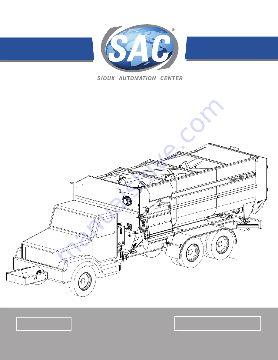
6190 FEED MIXER TRUCK

Summary of Contents for TURBO-MAX 6190

Page 1: ...nter IA 51250 Toll Free 1 866 722 1488 siouxautomation com OPERATION REPLACEMENT PARTS READ complete manual CAREFULLY BEFORE attempting operation MON600213 REV C 10 05 21 OPERATORS PARTS MANUAL TURBO MAX 6190 FEED MIXER TRUCK ...

Page 2: ...EV DATE BILL OF MATERIALS DESCRIPTION A 5 10 21 MON901048 ADD NOTE FOR PART NUMBERS TO USE PRIOR TO N08550 B 6 25 21 MON901108 ADD KN174724 QTY 4 KN174725 QTY 4 SPM821C7 QTY 2 SPM821R7 QTY 2 C 10 05 21 MON701640 MON900981 MON901025 ADD ON PAGES 51 54 AUX MIXER ELECT BOX AND SWITCH BOX ASSEMBLIES ...

Page 3: ...xerTruck Wefeelyouhavemadeawisechoiceandhopeyouarecompletelysatisfiedwith your new piece of equipment Your newTurbo Max Mixer Truck is a durable efficient and easy to use unit Proper care and use will result in many years of service INTRODUCTION Table of Contents General Information 3 Model and Serial Number Identification 4 Safety Signal Words 6 Equipment Safety Guidelines 7 Lighting and Marking ...

Page 4: ...operation Your model and serial numbers can be located on the front left hand side of the mixer Please copy this information and write them down inside of this manual This will allow easy reference if the ordering of parts should become necessary MODEL AND SERIAL NUMBER IDENTIFICATION ...

Page 5: ..._______ ______________________________________________________________________________________ ______________________________________________________________________________________ ______________________________________________________________________________________ ______________________________________________________________________________________ ____________________________________________...

Page 6: ...ury or death This signal word is to be limited to most extreme situations typically for machine components which for functional purposes cannot be guarded WARNING Indicates a potentially hazardous situation that if not avoided couldresultinseriousinjuryordeath andincludes hazardsthatareexposedwhenguardsareremoved Itmay also be used to alert against unsafe practices CAUTION Indicates a potentially ...

Page 7: ...S MANUAL AND HAVE DEVELOPED ATHOROUGH UNDERSTANDING OFTHE SAFETY PRECAUTIONS AND PROPER OPERATIONAL PROCEDURES Do not paint over remove or deface any safety signs or warning decals on your equipment Observe all safety signs and practice the instructions on them Never exceed limits of a piece of machinery If its ability to do a job or to do so safely is in question DON T TRY IT LIGHTING AND MARKING...

Page 8: ...e fitting clothing which may catch in moving parts Always wear protective clothing and substantial shoes It is recommended that suitable hearing and eye protection be worn Operator may come in contact with certain materials which may require specific safety equipment relative to handling of such materials Keep wheel and lug nuts tightened to specified torque Assure that truck tires are inflated to...

Page 9: ... at safe speeds Avoid overhead wires or other obstacles Contact with overhead lines could cause serious injury or death Avoid loose gravel rocks and holes they can be dangerous for equipment operation or movement Allow for unit length when making turns Do not walk or work under raised components or attachments unless securely positioned and blocked Keep all bystanders pets and livestock clear of w...

Page 10: ...sprockets can grab clothing or create pinch points which can cause severe injury or death to the operator or bystanders Always disengage the PTO driveline stop the truck engine and remove the ignition key so that the mixer cannot be accidentally turned on while inspecting servicing repairing or cleaning Following operation disengage PTO set brakes shut off engine and remove the ignition key Store ...

Page 11: ...r use a jack to support machine Always use proper tools or equipment for the job at hand Use extreme caution when making adjustments Follow torque chart in this manual when tightening bolts and nuts Never use your hands to locate a hydraulic leak on attachments Use a small piece of cardboard or wood Hydraulic fluid escaping under pressure can penetrate skin Openings in skin and minor cuts are susc...

Page 12: ...150 200 225 300 3 4 165 225 290 390 400 540 7 8 170 230 420 570 650 880 1 225 300 630 850 970 1310 Torquefiguresindicatedare valid for non greased or non oiled threads and heads unless otherwise specfied Therefore do not grease or oil bolts or capscrews unless otherwise specified in this manual When using locking elements increase torque values by 5 GRADE or CLASS value for bolts and capscrews are...

Page 13: ...ely Check for debris and or any other items that could block or affect machine operation Be sure that drain plugs are installed and the door is closed Top off the hydraulic oil reservoir if required B Test run the mixer Make sure mixer is empty then start the mixer Run for at least five minutes at recommended RPM Raise and lower the door and operate the conveyor slide tray several times Disengage ...

Page 14: ... accidents please read and understand this manual SAFETY Do not load hay without other dry commodities in the mixer first to act as a carrier or lubricant Do not overload hay content Sioux Automation Center Inc recommends up to 15 20 of hay by weight in the load Exceeding this percentage can decrease mixing performance or could potentially damage mixer and cause premature wear on driveline compone...

Page 15: ...ry commodities first corn silage second haylage last 4 Finish Loading Wet Commodities Any other wet feeds may be added at this time 5 Add Liquid Ingredients If ration includes water add it last Adding water at the beginning will cause the hay to bind LOADING AND MIXING Many different kinds of materials can be mixed with the Turbo Max Mixer but each kind of material has its own unique characteristi...

Page 16: ...pump control until the oil has warmed up HYDROSTATIC PUMP SYSTEM The augers and the reel are independantly powered by separate hydrostatic pumps which are powered by a single driveshaft from the engine The pumps can be set up for either CCW counter clockwise or CW clockwise rotation Typically if the pumps are mounted in front of the engine CCW pumps are installed and CW pumps are used if the pumps...

Page 17: ...manifold located behind the left front panel of the mixer body The hydraulic flow is directed to the different circuits found on the machine e g discharge door conveyor The valves are controlled electronically from the control console located in the truck cab In the event of power failure the valves can be controlled manually by depressing the button located on each end of each valve Manual Overid...

Page 18: ...ment Auxiliary Circuit Filtration Filter Replacement Auxiliary Circuit Filter 1 Make sure that the filter housing and filter are clean and free of any debris and other contaminates 2 Make sure that the replacement filter is the correct type for the application 3 Place a large drain pan or pail underneath the filter housing 4 Using a filter wrench remove the filter by turning the filter body counte...

Page 19: ...ess Standard of 18 13 Your mixer is equipped with an integral charge pump filter It is critical that this filter is changed on a regular basis to keep the system running normal The charge filter 1 per unit located on the hydrostatic pump next to the auxiliary pump must be changed within 20 hours of initial startup The filter must be changed again at 100 hours of use After the first two initial fil...

Page 20: ... to hose removal to keep foreign material out of the system Hose ends pump ports and fittings should be immediately capped upon removal of any hose or fitting to keep contaminants out of the hydrostatic system Do not use paper towels or rags to plug hoses or ports Lint can cause severe damage to pumps and motors Failure to keep out contaminants can result in system failure Each motor on the mixer ...

Page 21: ...minants Always remove any debris or foriegn material buildup away from the breather cap Remove and clean the breather cap every 200 hours of operation or twice annually or when ever servicing the hydraulic oil reservoir To maintain the breather cap follow this proceedure 1 Visually check the breather cap every day Remove any material that falls on top of the breater and surround ing areas Keep cle...

Page 22: ...to reverse the airflow on the radiator and should be used if there is a noticeable increase of dust or debris on the radiator or if there is a spike in the engine water temperature The hour meter registers how many hours the mixer is in operation The bunk light switch is an on off switch that controls the flip chute and rear bumper lights The master power switch supplies the electrical power to th...

Page 23: ...ing operation CONTROL CONSOLE AND DISPLAY Auger Speed Control Reel Speed Control Auxilliary Trnasmission Switch Reversible Fan Switch Bunk Light Switch Mixer Hour Meter Pump On Reel Power Switch Master Power Switch Auger Power Switch Door Control Joystick High Speed Cleanout Button ...

Page 24: ...EAD complete manual CAREFULLY BEFORE attempting operation CONTROL CONSOLE AND DISPLAY Door Spout Control Joystick The door control joystick controls both the feed door and the flip chute if so equipped Fuse and Relay Box Chassis Hour Meter ...

Page 25: ...STAL REVERSIBLE FAN 2 BUNK LIGHT 3 PUMP CONTROL 4 3 SPEED DROP BOX 5 OIL FAN AUX POWER POSITION TOP TO BOTTOM FUSE AMPERAGE 1 SCALE POWER 10A 2 CONTROL PEDESTAL REVERSIBLE FAN 15A 3 BUNK LIGHT 10A 4 PUMP CONTROL 15A 5 3 SPEED DROP BOX 10A 6 OIL FAN AUX POWER 15A 7 SPARE FUSE 10A 8 SPARE FUSE 10A 9 SPARE FUSE 15A 10 SPARE FUSE 15A FUSE PANEL RELAY AND FUSE POSITIIONS ...

Page 26: ...ghten if necessary Reel Wipers plastic strips which help material clean out of the reel hopper If the strips become bent back they can be unbolted moved turned around or replaced to improve clean out Wheel Bolts must be kept properly torqued Damage to the rim may occur if the wheel bolts are not checked frequently Rain can accumulate in the mixer if it is stored outside If rain has accumulated rem...

Page 27: ...about 100 hours breaking in change the oil in the gear units Check that there are no metallic parts with unusual dimension in the magnetic plug of the gear unit Change the oil in the gear unit while it is hot so that it is easier to drain Subsequent oil changes will be made every 1000 hours of operation or in any case each year Use synthetic ISO MOBIL SCH629 oil or equivalent ISO VG 220 gear oil D...

Page 28: ...G CAUTION 7 4 DEC111 DANGER AUGER 8 4 DEC118 WARNING HYDRAULIC PRESSURE 9 2 DEC202 SHIELD IN PLACE DECAL 10 2 DEC322 WARNING CHUTE AREA 11 1 DEC375 SAC MODEL SERIAL NUMBERS 12 1 DEC393 FEMA DECAL 13 1 DEC442 TURBO MAX LOGO RH 14 1 DEC444 TURBO MAX LOGO LH 15 1 DEC530 DOOR GAUGE 16 1 DEC623 POWERWASH NOTICE DECAL 17 1 DEC626 SAC LOGO 18 2 DEC777 6190 DECAL 19 1 DEC784 GREASE ROUTING INTERVAL 20 1 S...

Page 29: ...______ ______________________________________________________________________________________ ______________________________________________________________________________________ ______________________________________________________________________________________ ______________________________________________________________________________________ _____________________________________________...

Page 30: ...N701688 6190 LOWER AUGER 56 1 MON701693 LADDER 57 3 MON701694 6190 BUCKET GUARD 58 1 MON800308 END CAP 59 1 MON800531 MANUAL CANISTER 60 1 MON800539 AUGER MOTOR 61 1 MON800570 SPROCKET 62 360 MON800576 WEATHERSTRIP 63 1 MON800626 1 HYDRAULIC MOTOR 64 1 MON900770 REEL BEARING 65 1 MON901079 RH REAR DOOR 66 1 MON901080 LH REAR DOOR 67 2 NUT12LOCKNC 1 2 LOCK NUT 68 24 NUT12NC 1 2 NUT 69 12 NUT12NF 1 ...

Page 31: ...ING SPACERS 37 37 87 20 114 77 49 50 71 62 116 79 18 115 78 17 54 SPROCKET AS NEEDED POSITION GEARBOX FRONT PANEL 16 ON EACH SIDE OF FROM INSIDE OF BOX AUGER MOTOR TO BE MOUNTED ON OUTSIDE OF BOX REEL BEARING MOUNTED PLACE MON103692 ORIENTATION 72 108 8 11 66 55 MOUNT SPACERS ON A B NOTE SEAL ALL OILBATH SPACERS BEARINGS GREASE ZERKS AND PLANETARY WITH SILICONE 24 22 DETAIL B SCALE 1 8 23 59 96 75...

Page 32: ...ER DRIVE INSTALLATION 88 NOTE SEAL ALL OILBATH SPACERS BEARINGS GREASE ZERKS AND PLANETARY WITH SILICONE 31 78 74 67 74 67 CAN STILL ROTATE ON IT 100 33 46 97 104 101 3 109 73 12 100 97 101 29 104 46 3 109 73 IDLER INSTALLATION 12 TIGHTEN BOLT SO THAT TURNBUCKLE 53 FROM INSIDE OF MIXER REEL DRIVE INSTALLATION 70 6 58 103 1 42 60 108 7 72 63 REEL BEARING INSTALLED 84 ...

Page 33: ... OF THE DOOR OPENING THEN APPLY A COAT OF GREASE TO THE WEATHERSTRIP BUBBLE TO PREVENT IT FROM STICKING TO THE DOORS 112 113 15 76 112 113 15 76 57 81 98 102 91 96 92 96 94 NOTE APPLY CAULK TO THE CHANNEL OF THE WEATHERSTRIPPING 96 95 MON901074 BASE ASSEMBLY 92 GREASE HOSE TO UPPER REEL BEARING 92 GREASE HOSE TO LOWER REEL BEARING 60 GREASE HOSE TO UPPER AUGER BEAING 96 24 GREASE HOSE TO LOWER AUG...

Page 34: ...1685 AUGER TUBE 4 1 SAC14435 LEFT HAND FLIGHT 5 8 SAC14436 RIGHT HAND FLIGHT ITEM QTY PART DESCRIPTION 1 9 BURN13000158 GUSSET 2 2 MON104643 AUGER PADDLE 3 1 MON701394 AUGER SHAFT 4 1 MON701687 AUGER TUBE 5 3 SAC14437 1 2 LEFT HAND FLIGHT 6 2 SAC14439 5 8 LEFT HAND FLIGHT 7 2 SAC14441 3 4 LEFT HAND FLIGHT 8 1 SAC14442 3 4 RIGHT HAND FLIGHT FROM REAR 1 REAR 6 ROTATION FRONT 5 7 6 4 4 5 5 5 6 6 6 6 ...

Page 35: ...REEL ASSEMBLY ITEM QTY PART DESCRIPTION 1 90 BLT14X1NC 1 4 X 1 BOLT 2 36 BLT34X2NC 3 4 X 2 BOLT 3 9 MON104528 WIPER 4 1 MON701708 6190 TURBO 2 REEL WELDMENT 5 3 MON701710 6190 WIPER TUBE 6 90 NUT14NC 1 4 NUT 7 36 NUT34LOCKNC 3 4 LOCK NUT 8 90 WSH14FLAT 1 4 FLAT WASHER 9 90 WSH14LOCK 1 4 LOCK WASHER 4 8 3 2 26 1 6 26 5 20 ...

Page 36: ...F 1 SAC75999 TRUCK SCALE KIT HYDRAULIC TANK HEATER G 1 HYDBES19G8 120 VOLT 1500W TANK HEATER RAM KIT H 1 MON901000 2 MIXER REMOTE CONTROL KIT TO CHASSIS FRAME RAIL SUBFRAME 25 DO NOT WELD GUSSETS 4X TO SUBFRAME 25 25 8X BRACKET REPLACEMENT PART IS TWXPF38 FOR POLY FENDERS G E TO CHASSIS FRAME RAIL SUBFRAME 25 DO NOT WELD GUSSETS 4X TO SUBFRAME 25 25 8X BRACKET REPLACEMENT PART IS TWXPF38 FOR POLY ...

Page 37: ...PER N 1 VM900203 FRONT FEPTO BUMPER W ROLLER 1 VM900205 FRONT FEPTO BUMPER W POLE REMOTE AC CONDENSOR KIT P 1 MON900856 REMOTE AC BRACKET KIT DRIVELINE DROPBOX Q 1 MON900789 GEAR REDUCING GEARBOX KIT REVERSIBLE FAN KIT R 1 SAC56164 REVERSIBLE FAN CONTROL KIT CENTRI PRECLEANER KIT S 1 MON900976 KW T370 PRECLEANER KIT 1 MON900978 MACK 14 PRECLEANER KIT 1 MON901040 IH 7500 PRECLEANER KIT 1 MON901057 ...

Page 38: ...2 12 BLT38X114NC 3 8 X 1 1 4 BOLT 3 12 MON104365 SPACER 4 2 MON104637 TANK BRACKET 5 2 MON700844 CHECK ROD 6 1 MON701684 6190 TRUCK FRAME 7 2 MON900482 ADJUSTABLE CHECK ROD 8 4 MON901066 SCALE KIT 9 1 MON901074 6190 BASE ASSEMBLY 10 8 NUT34LOCKNC 3 4 LOCK NUT 11 12 NUT38NC 3 8 NUT 12 12 WSH38FLAT 3 8 FLAT WASHER 13 12 WSH38LOCK 3 8 LOCK WASHER 5 9 4 2 12 13 11 8 3 5 1 10 7 3 1 10 6 7 ...

Page 39: ...0 75 178 00 CENTER TO CENTER OF MOUNTS 10 DETAIL A SCALE 1 16 5 4 8 9 1 6 10 2 7 A 9 3 1 6 ITEM QTY PART DESCRIPTION 1 8 BLT34X212NC 3 4X2 1 2 BOLT 2 4 BLT58X8NCG8 5 8X8 NC G8 BOLT 3 2 MON101899 REAR ANGLE FRAME MOUNT 4 2 MON104100 FRONT ANGLE FRAME MOUNT 5 2 MON104101 SPACER TUBE 6 8 NUT34NC 3 4 NUT 7 4 NUT58LOCKNCG8 5 8 NC G8 LOCK NUT 8 4 STI701271 FRAME MOUNT SPRINGS 9 8 WSH34LOCK 3 4 LOCK WASH...

Page 40: ...______ ______________________________________________________________________________________ ______________________________________________________________________________________ ______________________________________________________________________________________ ______________________________________________________________________________________ _____________________________________________...

Page 41: ... 1 SAC73100 MAGNET GUARD 5 1 SAC73101 HINGE ROD 6 1 SAC74026 SLIDE TRAY 7 2 SPCP14X2 1 4X2 COTTER PIN 8 2 SPMAGNET1850 MAGNET 9 20 WSH14LOCK 1 4 LOCK WASHER 1 1 WSH78FLAT 7 8 FLAT WASHER 21 SLIDE TRAY SAC75010 1 4 3 6 2 5 ITEM QTY PART DESCRIPTION 1 9 BLT14X34ONC 1 4X3 4 BOLT TRUSS 2 9 NUT14NC 1 4 NUT 3 1 SAC73122 EXTENSION BELT 4 1 SAC75010 21 SLIDE TRAY 5 9 WSH14FENSS 1 4X1 1 4 FENDER WASHER 6 9...

Page 42: ... HYD6801 6 8 ELBOW ADAPTER 13 1 HYD6801 6 8R06 RESTRICTOR ELBOW ADAPTER 14 1 HYD6801 8 10 ELBOW ADAPTER 15 1 HYD6801 16 12 ELBOW ADAPTER 16 1 HYDC120 GAGE 17 1 HYDF11BA FILTER ASSEMBLY 18 1 HYDPMC8408 HYDRAULIC CYLINDER 8 ITEM QTY PART DESCRIPTION 19 1 HYDS25100RV3 TANK STRAINER 20 1 MON70489 1 HYDRAULIC HOSE 21 1 MON701490 HYDRAULIC HOSE 22 1 MON701491 HYDRAULIC HOSE 23 1 MON701492 1 HYDRAULIC HO...

Page 43: ...LIDE TRAY DOOR 4 5 2 5 1 MON800591 2 BANK VALVE W CHECK ITEM QTY PART DESCRIPTION 1 1 MON800591 1 2 PORT SUBPLATE 2 1 MON800591 2 CHECK VALVE 3 1 MON800591 3 BOLT KIT 4 1 VM800179 2 RELIEF VALVE 5 2 VM800179 3 12V DO3 VALVE 6 1 VM800179 4 VICKERS BOLT KIT PRESSURE FROM PUMP PORT P 6175 MOUNTING ORIENTATION LOOKING AT VALVE FROM BEHIND DISCHARGE 22 20 9 8 5 10 11 27 VALVE WITH SLIDE TRAY CIRCUIT LO...

Page 44: ...C HOSE 41 1 MON701544 HYDRAULIC HOSE 42 4 MON701627 HYDRAULIC HOSE 43 1 MON701629 HYDRAULIC HOSE 44 1 MON701630 HYDRAULIC HOSE 45 1 MON701631 HYDRAULIC HOSE 46 1 MON701643 POWER WIRE HARNESS 47 1 MON800618 HYDRAULIC MOTOR 48 1 MON800635 OIL COOLER 49 1 MON900946 HYDRAULIC TANK 50 2 NUT14WHIZ 1 4 SERATED FLANGE NUT 51 8 NUT38NC 3 8 NUT 52 2 PFBL11490EL 1 1 4 ELBOW 53 1 PFBL11490STEL 1 1 4 STREET EL...

Page 45: ...ASSEMBLY 8 39 37 34 53 54 56 9 49 CASE DRAIN FROM AUGER MOTOR OIL COOLER FROM HYD PUMP INLET 52 52 8 TO HYDRO CHARGE 18 40 INLET CASE DRAIN FROM PUMP 21 BREATHER CAP PART HYDAS10XL SIGHT GLASS PART STI702230 8 39 37 C FROM AUG OIL COOLER FROM HYD 52 52 8 18 48 40 INLET CASE DRAIN OUTLET 39 13 FROM PUMP TO HYD OIL RESERVOIR 21 ...

Page 46: ...20 13 41 13 35 TO HYD OIL COOLER RETURN PORT A MOTOR RETURN FROM HYD OIL RESERVOIR PUMP 1 PUMP 2 PORT L TO REEL TO AUGER MOTOR 57 NOTE CONNECT WIRE HARNESS WITH ORANGE WIRE TO PUMP 1 CONNECT WIRE HARNESS WITH BLUE WIRE TO PUMP 2 42 42 35 6 24 38 CASE DRAIN FROM REEL MOTOR 13 TO REEL MOTOR PUMP 2 PRESSURE PORT B PRESSURE PUMP 1 TO AUGER MOTOR PORT R 10 17 PUMP 2 57 ...

Page 47: ...6 1 TO PORT B PUMP 2 PUMP 2 RETURN TO HYD OIL REFERENCE ONLY TO PORT A MOTOR SHOWN FOR 22 59 2 35 30 35 42 30 38 FROM PORT A PUMP 1 5 11 16 60 PRESSURE RETURN 47 42 FROM PORT B PUMP 1 21 23 31 3 50 43 14 26 15 44 45 27 22 NOTE LOOP FLUSH VALVE MUST BE PROPERLY ADJUSTED TO 1 5 2 GPM OF FLOW AT HIGH IDLE AND AT LEAST 150 PSI OF CHARGE PRESSURE AT LOW IDLE WITH AUGER CIRCUIT PUMP FULLY STROKED ...

Page 48: ...ING BRACKET 12 1 MON101479 HYDROSTAT MOUNT 13 2 MON104152 CHANNEL MOUNT END CAP 14 1 MON104243 OIL COOLER MOUNT 15 1 MON104315 FLANGE ADAPTER ITEM QTY PART DESCRIPTION 16 1 MON800592 HYDRO PUMP 17 1 MON800610 TANDEM HYDRO PUMP 18 1 MON900994 HYDRO HOOD KIT 19 2 NUT12LOCKNF 1 2 FINE THREAD G8 LOCK NUT 20 4 NUT12NCG8 1 2 NC G8 NUT 21 4 NUT34NC 3 4 NUT 22 4 NUT38NC 3 8 NUT 23 2 NUT516LOCKNC 5 16 LOCK...

Page 49: ...2 1 88 CAPZERK CROSS 4 1 PTO3 2 119 FLANGE YOKE 5 2 PTO3 70 28X PTO U BOLT 6 4 BLT38X1NF 3 8X1 G8 FINE THRD BOLT 7 4 WSH38LOCK 3 8 LOCK WASHER VM900218 HYDRO DRIVELINE BE ALIGNED YOKES MUST 5 1 5 2 4 6 3 1 19 X 6 78 Y X 12 09 2 19 ITEM QTY PART DESCRIPTION 1 2 PTO4 2 669 FLANGE YOKE 2 1 PTO4 3 1241KX SLIP YOKE 3 1 PTO4 28 307 TUBE YOKE 4 1 PTO4 40 761 SLIP YOKE 5 2 PTO5 155X CROSS 6 6 WRM312X095DR...

Page 50: ...L RING 23 1 STI701245 100 AMP SLOW BLOW FUSE 24 1 STI701247 FUSE BLOCK 25 120 STI701743 BLACK BATTERY CABLE 26 1 STI701962 VACANT SWITCH PLUG 27 240 STI702453 1 2 BRAIDED WIRE LOOM 28 120 STI703630 RED BATTERY CABLE 29 1 VM100667 BOTTOM CONSOLE COVER 30 1 VM700235 JOYSTICK SWITCH 31 1 VM800254 PEDESTAL BASE TUBE 32 1 VM800255 CONSOLE ARMREST 33 1 VM800256 ARMREST PAD 34 1 VM800309 CONSOLE BASE 35 ...

Page 51: ... 37 28 STIWIRE14PR06 14GA BROWN WIRE 38 20 WTIWIRE14PR37 14GA PURPLE WIRE 39 20 STIWIRE14PR39 14GA GREEN WIRE 40 30 STIWIRE18PRBL 18GA BLACK WIRE 41 30 STIWIRE18PRR 18GA RED WIRE 42 1 VM800174 10A MINI RELAY FUSE 43 4 WSH316LOCKSS 3 16 LOCK WASHER STAINLESS ITEM QTY PART DESCRIPTION 1 6 BLT14X34ONC 1 4X3 4 SLOTTED TRUSS BOLT 2 1 DEC704 POS NEG TERMINAL DECAL 3 1 DEC705 RELAY FUSE DECAL 4 5 JES2971...

Page 52: ...BLUE 4 PIN A3 BUNK LIGHTS POWER 14GA BROWN 1 SCALE GROUND BROWN SCALE POWER RED RELAY SCHEMATIC PIN B9 PIN B10 PIN D9 PIN D10 14GA GREEN PIN A6 PIN B1 PIN B2 14GA BROWN SPARE CNTRL PED REV FAN POWER 14GA YELLOW OIL COOLER FAN AUX POWER 14GA GREEN 1 RELAY POWER FUSES PIN D7 PIN D5 PIN D3 PIN D1 PIN B8 PIN B6 PIN B4 PIN D8 PIN D6 PIN D4 PIN D2 PIN B7 PIN B5 PIN B3 PIN A5 80 AMP MAX CURRENT 14GA BLUE...

Page 53: ...SWITCHES AND ACTUATORS 9 ENTRY POINT OF HARNESS IS THROUGH THE RECTANGULAR CUTOUT 10 IN THE FRONT OF THE BOX ROLL EXCESS LENGTH OF WIRE HARNESS UP AND ZIP TIE TO BOX 11 11 10 15 5 14 13 12 8 1 24 4 2 18 23 21 22 22 22 19 19 20 ITEM QTY PART DESCRIPTION 14 4 SPMB1032X12 10 32 X 1 2 MACHINE SCREW 15 4 SPMX10X1 10 X 1 METAL SCREW 16 1 STI700279 10 8GA TERMINAL RING 17 1 STI700291 18 22 GA FEMALE SPAD...

Page 54: ...ED 5 PLACE 2 OF HEAT SHRINK OVER EACH RING TERMINAL CRIMP END 6 NOTE NO LOOM AREAS AND LENGTHS 7 INSTALL CAVITY PLUGS IN UNUSED DT CONNECTORS AS NOTED 8 ITEM QTY PART DESCRIPTION 20 180 STIWIRE14PR02 14GA RED WIRE 21 292 STIWIRE14PR03 14GA BLUE WIRE 22 292 STIWIRE14PR04 14GA ORANGE WIRE 23 66 STIWIRE14PR05 14GA YELLOW WIRE 24 66 STIWIRE14PR06 14GA BROWN WIRE 25 66 STIWIRE14PR15 14GA YELLOW RED WIR...

Page 55: ...6 1 SCA404930 JUNCTION BOX 7 30 SPCABLETIEMED CABLE TIE 8 10 WSH14LOCK 1 4 LOCK WASHER MON900725 HD REAR BUMPER KIT 4 5 6 3 8 1 2 4 NOTE SCALE POWER HARNESS AND JUNCTION BOX CABLE SCA170008 AND SCA170053 ARE CONTAINED WITHIN CONTROL CONSOLE KITS ITEM QTY PART DESCRIPTION 1 10 BLT14X34NC 1 4X3 4 BOLT 2 10 NUT14NC 1 4 NUT 3 1 SCA170026 REMOTE INDICATOR BRACKET 4 8 SCA170030 LOADCELL SHIM 5 4 SCA4032...

Page 56: ...1 2X48 PIPE 9 1 SAC56071 BUMPER ROLLER 10 1 TW62590 BUMPER MARKER 11 2 VM100314 BUMPER MOUNT 12 2 VM100315 CHANNEL MOUNT 13 1 VM700109 BUMPER WELDMENT 14 60 WRM8CHANNEL 8 CHANNEL 15 10 WSH34LOCK 3 4 LOCK WASHER 16 4 WSH58LOCK 5 8 LOCK WASHER ITEM QTY PART DESCRIPTION 1 4 BLT34X2NC 3 4X2 BOLT 2 6 BLT34X212NC 3 4X2 1 2 BOLT 3 2 BLT38X114NC 3 8X1 1 4 BOLT 4 4 BLT58X2NC 5 8X2 BOLT 5 10 NUT34NC 3 4 NUT...

Page 57: ...APPLICATION 3 PAINT WELDED PARTS BLACK AFTER ASSEMBLY ITEM QTY PART DESCRIPTION 1 16 BLT516X114NC 5 16X1 1 4 BOLT 2 2 MON701560 TANDEM FENDER WELDMENT 3 16 NUT516NC 5 16 NUT 4 8 RP100021 GUSSET 5 4 SAC56009 MUD FLAP STRAP 6 1 SACFLAP24X36 MUD FLAP 7 16 WSH516LOCK 5 16 LOCK WASHER 7 6 5 FOR BRACKET IS TWXPF38 4 3 REPLACEMENT PART 1 2 ITEM QTY PART DESCRIPTION 1 8 BLT516X114NC 5 16X1 1 4 BOLT 2 8 NU...

Page 58: ... WEATHERPACK CAVITY PLUG 10 4 KN174724 RIGHT ANGLE CONNECTOR 11 4 KN174725 OVAL LIGHT GROMMET 12 2 MON104325 BUNK LIGHT BRACKET 13 2 MON800487 AMBER CLEARANCE LIGHT 14 2 NUT516NC 5 16 NUT 15 4 SPB14250 2 WIRE CONNECTOR PLUG 16 4 SPB14318 FLUSH ROUND GROMMET 17 2 SPM821C7 CLEAR BACKUP LIGHT 18 2 SPM821R7 RED STOP LIGHT 19 48 STI14SHRINK 1 4 HEAT SHRINK TUBING 20 6 STI700200 1 2 LOOM CLAMP 21 2 STI7...

Page 59: ...ROWN BROWN RED GREEN YELLOW BLACK GREEN WHITE WHITE YELLOW BROWN BLACK WHITE WHITE WHITE GREEN WHITE RED CLR LT RED CLR LT AMBR CLR LT WHITE REAR CLEARANCE AMBR CLR LT FR BUNK LIGHT RED TAIL LT RED TAIL LT WHITE REV LT LIGHT RR BUNK WHITE REV LT DISCHARGE LIGHTS SIDE 4 BLACK NOTES HEAT SHRINK SOLDER ALL EXPOSED WIRES 1 SPLICE ALL WIRES INTO TRUCK HARNESS EXCEPT BUNKLIGHTS 2 GROUND BUNK LIGHTS TO C...

Page 60: ... 1 MON102641 LOADCELL BRACKET 5 2 MON104366 WEIGHBAR RETAINER 6 1 NUT34JAMNC 3 4 JAM NUT 7 1 NUT38NC 3 8 NUT 8 6 NUT58NC 5 8 NUT 9 2 WSH34FLAT 3 4 FLAT WASHER 10 2 WSH58FLATG8 5 8 FLAT WASHER 11 6 WSH58LOCK 5 8 LOCK WASHER Page 60 OPERATION REPLACEMENT PARTS READ complete manual CAREFULLY BEFORE attempting operation 9 8 11 5 3 4 10 2 2 5 11 8 6 9 1 ...

Page 61: ...57 58 SPECIFICATIONS Reel Diameter 70 70 76 82 Reel Hopper Thickness 3 8 3 8 3 8 3 8 Lower Auger Flighting Diameter 24 24 24 26 Flighting Thickness3 5 8 5 8 5 8 1 2 5 8 3 4 Tube Outside Diameter Wall Thickness 6 5 8 3 4 6 5 8 3 4 8 5 8 1 2 8 5 8 1 2 Drive Shaft Diameter 4 4 4 4 1 2 Upper Auger Flighting Diameter 22 22 24 26 Flighting Thickness 1 2 1 2 1 2 1 2 Tube Outside Diameter 6 5 8 3 4 6 5 8 ...

Page 62: ...aler is specified as labor done at the SAC factory or SAC authorized dealer ONLY SAC will pay the common carrier freight expense of parts to and from the owner Faster freight service is available with the owner paying the difference in cost between common carrier and preferred method by owner Freight of whole goods to or from the factory is the owner s expense regardless if they fail under warrant...

Page 63: ...ges when any party other than SAC performs the replacement or repair of parts claimed to be defective nor shall this warranty apply to an SAC product upon which any alterations or repairs other than normal maintenance have been made without the written approval of SAC SAC shall in no event be liable for consequential damages lost profits or contingent liabilities arising out of the failure of any ...

Page 64: ......

Reviews: