192
CDI UNIT
Removal
Remove the battery cover and the battery.
Disconnect the connector and remove the CDI unit.
Inspection
System inspection
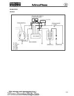
Disconnect the 5- pole connector from the CDI unit and test the wires at the harness- side connector according to the table be-
low:
Item
Measure at:
Standard
Ignition coil (primary)
Black/Yellow - Green
circa 1
Ω
Signal generator coil (pick up)
Blue/white - green
circa 150
Ω
Exciter coil
Black/red - green
circa 550
Ω
Ignition switch
Black/white - green
There should be continuity at the switch OFF and no continuity
at the swith ON.
Ground
Green - frame ground
There should be continuity.
If any one item does not meet the standard, test the individual component and replace it or repair open short circuit in wire or loose
connector as required.
IGNITION SYSTEM
Summary of Contents for madass
Page 53: ...50 LUBRICATION SYSTEM...
Page 111: ...10 12 Nm 10 14 Nm 108 CYLINDER PISTON...
Page 112: ...109 ZYLINDER KOLBEN...
Page 129: ...1 2 126 CLUTCH GEARSHIFT LINKAGE Remove the primary drive clutch 1 and clutch center guide 2...
Page 191: ...PICK UP KILL SWITCH RPM STOP B R G G G Bl W 188 IGNITION SYSTEM SCHEMA...
Page 192: ...PICK UP KILLSCHALTER DREHZAHLBEGRENZER Z NDANGLEICHER B R G G G Bl W 189 Z NDSYSTEM DIAGRAM...


