92
CYLINDER HEAD / VALVES
Valve guide
NOTE
Ream the valve guide to remove the carbon build-up before
checking the valve guide.
Always rotate the reamer clockwise, never counterclock-wise
when installing, removing and reaming.
Measure and record each valve guide I.D. with a ball gauge or
inside micrometer.
SERVICE LIMIT:
IN/EX: 5.03 mm
Calculate the stem-to-guide clearance.
SERVICE LIMIT:
IN 0.08
mm
EX: 0.10
mm
NOTE
If the stem-to-guide clearance exceeds the Service limit,
determine if a new guide with Standard dimensions would
bring the clearance within tolerance. If so, replace the guides
as necessary and ream to fi t.
If the stem-to-guide clearance still exceeds the service limit
with new guides, replace the valves and guides.
Reface the valve seat whenever new valve guides are
installed.
VALVE GUIDE REPLACEMENT
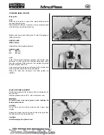
Chill the valve guides in the freezer section of a refrigerator for
about an hour.
Heat the cylinder head to 100°C with a hot plate or oven.
WARNING
To avoid burns, wear heavy gloves when handing the
heated cylinder head.
CAUTION
Do not use a torch to heat the cylinder head; h may cause
warping.
Support the cylinder head and drive out the valve guide from
the valve port with a valve guide driver.
CAUTION
Avoid damaging the cylinder head.
Summary of Contents for madass
Page 53: ...50 LUBRICATION SYSTEM...
Page 111: ...10 12 Nm 10 14 Nm 108 CYLINDER PISTON...
Page 112: ...109 ZYLINDER KOLBEN...
Page 129: ...1 2 126 CLUTCH GEARSHIFT LINKAGE Remove the primary drive clutch 1 and clutch center guide 2...
Page 191: ...PICK UP KILL SWITCH RPM STOP B R G G G Bl W 188 IGNITION SYSTEM SCHEMA...
Page 192: ...PICK UP KILLSCHALTER DREHZAHLBEGRENZER Z NDANGLEICHER B R G G G Bl W 189 Z NDSYSTEM DIAGRAM...


