background image

Summary of Contents for SA 2-440

Page 1: ... SJ SACHS Repair Instructions No 4072 8 E SACHS SA 2 440 Snowmobile Engine Edition December 1970 FICHTEL SACHS AG D 8720 SCHWEINFURT ...

Page 2: ......

Page 3: ... 33 35 Corburettor Decorbonizing the exhaust muffler the cylinders ond the cylinder heads Assembling the engine _ Ignition timing Engine with BaSCH Bendix pinion type electric starter type DG Operation mointenance ond lubricotion of the electric storter Storter Fa ults Instructions end wiring diegram for magneto generator 12 V 40 W ond 12 V 75 W 36 Instructions ond wiring diogram for mogneto gener...

Page 4: ...nents in detail will also be found helpful when used in conjunction with this booklet Naturally good maintenance and repair work and efficient servicing call for good equipment a well equipped workshop and skilied personnel Dealers are requested to make this manual and all SACHS Service Bulletins which contain technical modifications available to every individual responsible for actual servicing T...

Page 5: ... z cn I r r I 0 I Z c 3 l T1 Z cn 0 z cn F e F 1 _L t l l I f If x ö i ...

Page 6: ...tO ured 01 11 boro tri pr u 01 b _ 760 mm HiI on I on oi temperatur of L _ 2O C 68 FI ilh toleronee 01 S Fot date minin Ihe pow output o cording 1o Ge mon Stondord DIN 6270 bo 736 mm Hg ond l 2O C Ihe IlbovI outp t h lo b multiplied by Ihe orr erio 10 0 0 97 In he in u 01 ledoni ol p ogr 1 r rv h r 1o introd ce modilicotionl wilhout noti l ...

Page 7: ...098 0 0118 in l 3 50 4 00 mm before TDC 0 1378 0 1575 in Contocl breoker gop 0 4 0 05 mm 0 016 0 002 in Pole shoe gop Siopped engine Running engine 25 29 mm 0 9843 1 1417 in l 7 11 mm 0 2756 0 4331 in Spork plug BOSCH W260T2 orW240 T 1 see note on poge 24 Corburetlor TlllOTSON diophrogm corburellor HO 131 1 0 38 10 mm Corburellor settina Moin jel 1 1 lurns open Idl ing jet 1 lurn open Air inloke v...

Page 8: ...REPAIR TOOLS AND ASSEMBLY JIG n 11 8 Ä 1 7 8 2 17 9 4 3 tj 7 5 6 10 8 9 11 13 21 14 16 r ri C1i 18 12 15 17 4 ...

Page 9: ... gudgeon pin extroctor locoting pin for piston WithdrowoJ 1001 Fitting tool for flonged hub Retaining fork Retoining lever Ignition timi ng gauge Adjusting pin for flyweight Torque wrench Revolution counter Extroctor sleeve ossy Hex head bolt replocement ports Threoded sleeve f Thrust beoring for 1476 013 000 Clomping ring 58 mm I D Extroctor shells for cylindricol roller beoring inner roce NJ 206...

Page 10: ... stack carburettor and recoil starter Fig l Mount engine on assembly i i repair tools no 18 19 20 o nd 21 with 2 hex head bolts M 0 x 30 os shown in the illustration Screw off intoke stack 5 with reinforcement ring 4 Pull off impulse pipe 2 Remove carburettor 3 ta king core of insulati ng sleeves a nd go ket Unscrew recoi l starter 1 to gether with inserted labyrinth ring V pulleys and V belt Fig ...

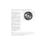
Page 11: ... Reposition retaining lever os shown in the illustration end re move mogneto Ilywheel 2 by means cf withdrowol taoI 1 re pair taoI no 4 Remove Woodruff key from crankpin Fan housing fan end armature plote Fig 5 Unscrew fan housing 2 end take out Ion 1 sliding lit Detoch leads fram ormoture plote 3 ot the terminals ond unscrew ormature plote Fig 4 Fig S 7 ...

Page 12: ...ew exhoust tubes 1 with on ordinory strap wrench only if neeessory Unserew eylinder heeds 3 end remove eylinder heod ge skets AHention Mark eylinder ond piston power lakeoff side tagether Remove eylinders 2 end eylinder flonge gaskets Note The Alu Chrome l cylinders eon not be rebored eylinders end pistons are divid ed info tolerance groups A B and C Mount only pistons and eylinders which belong 1...

Page 13: ...necting rod eye Note When replocing needle bearings wolch toleronce mark on con necting rads see spore paris lisll Unscrew crankcose from as sembly jig Crankcase and crankshaft Fig 10 Unscrew Ihreaded nipple 11 ond screw plug 21 Unscrew 12 nuts from lower part of crankcose Split crank case by slightly top Fig 10 ping with 0 rubber mallet Fig 1 1 Remove ail seals 1 and 3 take out cronkshaft 4 both ...

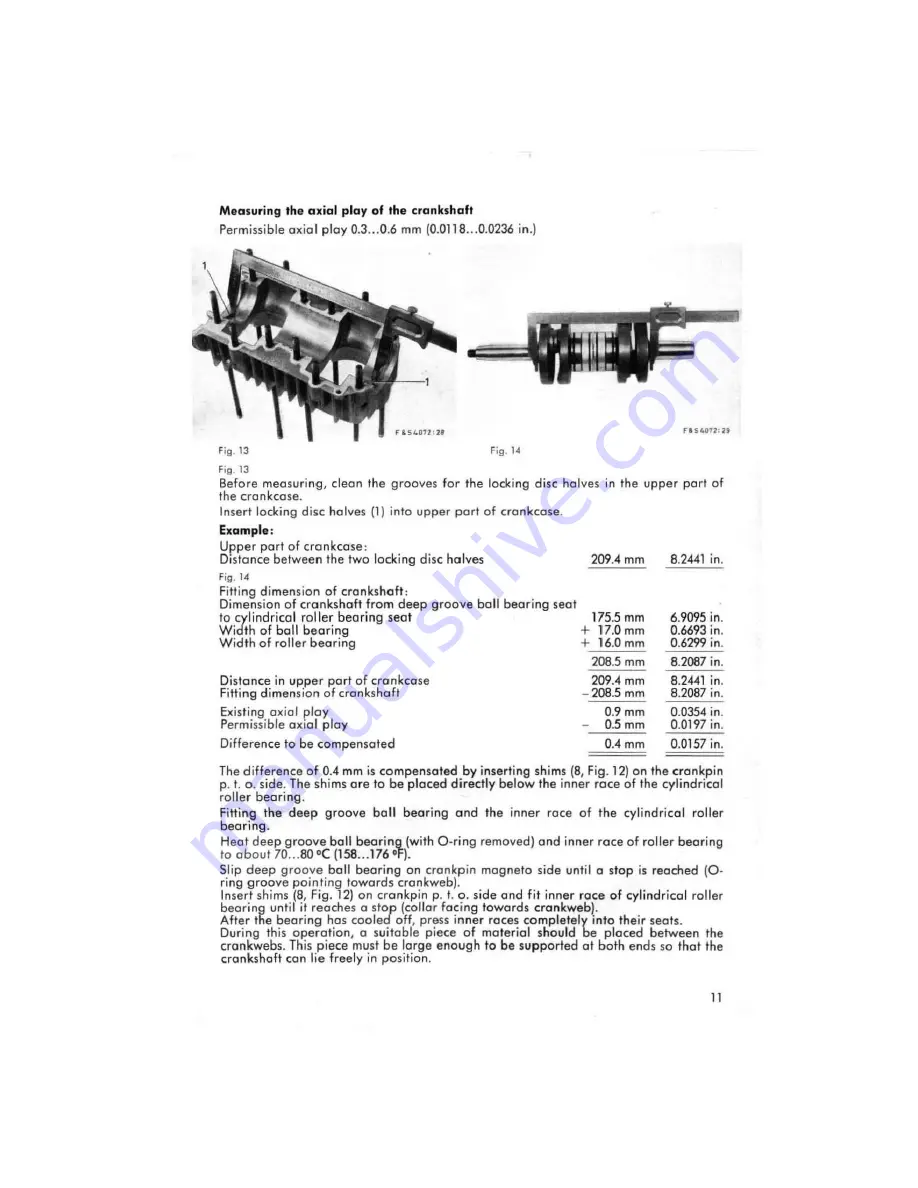
Page 14: ...earings 4 Fe S 4072 27 Fig 12 Remove outer race 4 cf cylindricol roller bearing end roller eoge from inner roc e 1 01 beoring Remove inner race 1 of cylindricol roller bearing ond the deep groove ball bearing 7 by meons of suitable edrector shells 5 end 6 clamping rings 2 ond extroctor sleeve 3 repoir tools no 12 13 14 15 16 ond 17 Remove shims Bl A ention If shims have been domoged during the ope...

Page 15: ...87 in 8 2441 in 8 2087 in 0 0354 in 0 0197 in 0 0157 in The difference of 0 4 mm is compensated by inserting shims 8 Fig 12 on he crankpin p t o side The shims are to be placed directly below the inner roce of the cylindrical roller bearing Fitting the deep 9roove ball bearing and the inner race of the cylindrical roller beari ng Heot deep 9roove ball bearing wilh 0 rin9 removed ond inner roce of ...

Page 16: ...groove ball beerings by slightlY knocking the housing ogoinst 0 wooden sup port Take core of wosher be tween the beorings Note t Remove lock ring in bearing seat only if necessary Mtallation F i11 deep gtöove ball bearing half with high temperature bearing grease Take care when instolling thot the encosed sides Ji P pointing towords the outside Force first deep groove ball bearin g into the warm h...

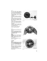
Page 17: ...core of disc 3 Fig 191 Remave rope from pulley Fig 18 Reise spring end 10 toke out coil spring Hold coil spring firmly with both thumbs see illustrotion end by roising eoch thumb let out spring o oltl ro 0te sides Note Replece bush 1 Fig 201 only if necessary using the extroctor shells clamp i n ring and ex tractor sleeve repair tools no 15 13 ond 121 Take care of toleronce ring in bush I Fig 201 ...

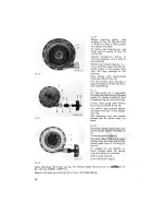
Page 18: ...moved lIonged sleeve B stop 4 lIonged sleeve 7 starter handle 5 ond clamping ring 6 onto Ihe rope Iamp rope guide with filI ister heod cop screw 9 M 4 x 10 lay starter rope around clomp ing taper and pull it into clamp ing ring Pull clamping ring into starter handle and let sta rter rope run back Fig 22 lubricate starter pawl bed and starter powls ligMly with SAE 10 oil Fit starter powls 4 ond 5 T...

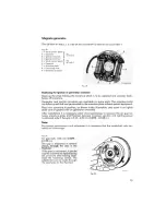
Page 19: ...ial equipment Ploce new ormature in position os shown in the illustration ond screw it on Iightly toke core cf ground wire on generator armatureJ After installation it is necessary under all circumstances 10 measure the air gap be tween armoture p 0les and flywheel because maximum ignition and lighting power is oblained only 1I Ine gap is 0 25 0 35 mm 0 0098 0 0138 in Note Far correct meosurement ...

Page 20: ...wedge in the slider BOSCH greose is available in tubes at all BaSCH suppliers Da not allow any grease or oil to reach the contacts Replacing the capacitor 1 Unsolder leads 2 Push the capacitor out of the armature plote with a round piece of wood 3 Remave the caulked spots from the hole with a scraper 4 Insert new copacitor ond carefully caulk agoin 5 Solder both leads to their terminals Replacing ...

Page 21: ... woshers Fig 26 Toke lock ring 7 flyweight 6 ond thrust washer below off from bearing pin Greose bearing pin ond bearing surface of flyweight in flywheel slightly with BOSCH greose Ft 1 v 26 Fit thrust washer 0 3 mm 0 0118 in thick on bearing pin insert spring 2 in flyweight Fit flyweight on bearing pin must engage with cam end se eure with lock ring 7 Cam end flyweight must olwoys be freemoving P...

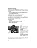
Page 22: ... fuel feed is restricted insufficient lubricont will be conveyed to the moving parts of the engine With a two stroke engine the carburettor setting should olwoys be sufficient 10 provide odequote lubricotion Only 0 correctly odjusted corburettor wil l ensure low fuel consumption and on opti mum of economicol operation Adjusting the carbureHor for special climatic conditions Wnen using the engine a...

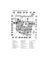
Page 23: ...sing 24 Diophrogm housing 38 Oullel valve on pump 14 Throol of carburellor venturi 25 Diaphrogm diaphragm IS Moin fueJ autlel 2 Air chambar Fuel pump gaskel 16 Choke 27 Filter gosket 5 Diophragm housing gasket 17 FueJ passage rom pump 28 Fuel strainer 6 Conlrol chamber 10 conlrol chomber 29 Filter housing screw 7 Ad justing screw for idJing jet J8 Inlet needle ond seol 3 Fuel chamber 8 Impulse pos...

Page 24: ...wed tao fight into the seat i e closedl 0 5 th is will deform the seato Initial adjustment F SL072 31 Fig 28 Fig 29 Far initial odiustment close the odjusting screw for the main iet 1 Filii 28 end the adjusting screw for the idling iet 3 Fig 29 turn in clockwise direction Idl 0 light stap is encauntered Then turn the odiusting screw far the mein iet bock egoin 1 turns the ediusting screw af t e id...

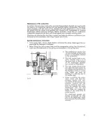
Page 25: ... fitting the inlet control lever and the compression spring see illustration make sure that both ends of the spring are embedded in the spring seats Fig 30 3 The compression spring mus not be stretched os the spring tensio n is accurately adiusted to the carburettor 4 The inlel control lever is cor rectly inserted when it is at he same level os the bottom of he diaphragm chamber see arrows on illu...

Page 26: ...10 red heot by meons cf 0 we lding forch cr in 0 farge fire I The exhaust system should not be modified as any such a lterations wi ll be detri mental to performance and fuel consumption and will increase the exhoust noise Any modifications of the exhaust system are moreover illegal and constitute a punishable offence Cylinder head Unscrew the cylinder heods and remove the carbon deposits from the...

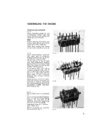
Page 27: ...fere fitting Ihern A so smeor the seoling lips slightly with tllis grease Fit oil seal 13 23 6 x 62 x 10 on crankpin magneto side end oil seal 1 28 4 x 62 x 10 on eronk pin p t o side flush with Ihe outer edge of Ihe cronkcose Sealing lips focing towords cronkweb Smear sealing surfaces in cronk case with sealing compound we recommend sealing compound No 1073 supplied by Mssr s Ernst Sonderhoff D 5...

Page 28: ... 80 158 176 F ond fit it by meens of the gudgeon pin ex troctor 3 repoir tool no 1 end insert 2 repair 1001no 2 Remave the loeating pin Cover the cronkcose ond insert 4 wire ci rclips Cylinders ylinder heads and exhaust tubes Fig 36 Fit cyli nder flange goskets ce cording to Ihe shope of the trans fer ports Ploce pistons on slotted wooden boord 4 Fig 35 ond fit the ey linders which should be sligh...

Page 29: ...ilIister heod cop screws M 6 x 30 and spring woshers Carburettor and intake stack Fig 37 Fit gaskets end both insu lating sleeves on upper part of intake manifold and fasten carburettor with two self Iocking nuts M 8 T ghten ng torque 0 8 1 1 kpm 5 8 8 0 ft Ib Fit impulse pipe to nipple 4 Fig 32 and carburettor connection 2 Fig 29 Fasten intake stock 5 Fig 1 and reinforcement ring 4 Fig 1 with 3 f...

Page 30: ...isler head cap screws 4 M 6 x 30 ond 1 filIister head cop screw 2 M 6 x 75 with spring washers moke sure that the covers are propedy seoled Tightening lorque for filIister heod screw M 6 x 30 0 5 0 6 kpm 3 6 4 3 11 Ib Tightening torque for filIister head cap screw M 6 x 75 1 5 2 0 kpm 10 8 14 4 11 Ib Fig 41 Screw both cylinder cover ho lves logelher wilh Ihreoded ball 2 M 6 x 182 Iocked wilh 2 nul...

Page 31: ...key engages occurately with the groove in the flanged hub Use retaining lever to hold the mogneto flywheel os shown in Fig 4 and fasten it with washer end nut M 14 x 1 5 the ehamfered side of the wosher faeing towards erankpin toper Tightening torque 11 0 12 0 kpm 79 6 86 8 ft Ib Ignition timing Fig 43 Firing point Stopped engine 0 25 0 30 mm 0 0098 0 0118 in before TDC Running engine 3 5 4 0 mm 0...

Page 32: ...ght stap is en countered 3 When adiusting the spark od vonce it has to be borne in mi nd that Ihe spark plug pas soges are inclined 01 an angle of 300 towards the piston bearing surfaces Therefore 0 correspondingly higher value has to be odopted os shown in Fig 45 300 scole A Example II the liring point is 3 5 4 0 mm 0 1378 0 1575 in belore TDC scale C the value to be adopted is 4 0 4 6 mm 0 1575 ...

Page 33: ...ith the mark 1 Fig 43 on the fan housing 4 Turn the magneto fl ywheel slightly in direction of rotation the contoct brecker 5 Fig 23 for cylinder 1 should now begin 10 open If not the firing point can be corrected by turni ng the armature plate This can be done by means of the longi tudinal slots Turning the armature plate cgainsl the directian of rotation advances Ihe ignition turning it in direc...

Page 34: ...en pulley with 3 filIister heod cop screws M 6 x 15 end spring washers Tightening torque 0 8 1 1 kpm 5 8 8 011 Ib l Insert shims 2 os required they serve Jo odjust the tension of the V beltl Fig 49 Fit se ond idler pulley hall 111 Use retoining fork 2J as shown in the illustration and tighten nut M 14 x 1 5 together with spring washer Tightening torque 4 0 4 5 kpm 28 9 32 5 If Ib l Check V bell te...

Page 35: ...2 ond spring woshers os shown in the illustration Electrical Connections Fig 50 After instolling the engine restore the electrical wires from frame 10 engine 10 their terminals Fasten cover wilh inscription SACHS 10 cylinder cover half intoke side with 5 filiister heod cop screws M 6 x 38 end spring weshers end place rubber boots with ignition leads into the recesses of the cover 31 ...

Page 36: ...ive for cranking the engine As 500n os the engine starts the pinion is driven by the engine at a speed greater thon that of the motor spindie When the starter switch is releosed the pinion is spun back olong the screwed spindie assisted by spring tension is put out of engageme nt and returns to rest position The overrunning roller clutch prevents premature pinian disengagement Removal Fig 51 Unscr...

Page 37: ...Da not leave the starter switehed on for more thon 10 seeonds without interruption Before switching on again woit 1 minute to allow the starter to cool and the bottery to reeover If there is 0 dashing of teeth switch off immed iotely and repeat the proeess Release the starter switch os soon os the engine ru ns under its own power If the equipment is not provided with 0 starter safety deviee da not...

Page 38: ...rbon brushes When fitting the carbon brushes moke su re that the spring does not hit the brush When fitti ng the cover make sure thot the armature shoft end the ermature itself are seoted properly in the housing and that the carbon brushes rest on the commutotor Fit shims end reta iner ond fasten the cover When giving the engine 0 general overhaul it is edvisable to replace the carbon brushes Comm...

Page 39: ...arben brushes cf starter da not ie on the commutator are jommed in their guides are worn broken fou led or dirty 6 Starter switch domoged Ieese perls 7 Voltcge lass in leads too great leads domoged lead connections 100se B When he starter is switched on the armature shaft rotates but the engine does not start I Bottery insufliciently cho ged 2 Pressure of carbon brushes not sufficient 3 Voltage la...

Page 40: ...an af 0 75 mm1 In order to ovoid valtoge lasses in long leads use wires of 1 0 mmJ cross section for connections at the terminal blocks are should also be token to ensure 0 good ground connection from the engine via the chassis to the lomps The following are the symbols used in the wiring diogram on poge 37 AI lighting lood 12 V 40 W A Resistonce 12 V 35 W for 75 W system wilh 40 W light 811 Ignit...

Page 41: ...1 11 1 I I H I I A ro I cr 1 L L I J l t 1 I r l _ _ J 37 ...

Page 42: ...s more thon 1 m Care should also be taken to ensure a good ground connection from the engine via the chassis to the lamps The following are the symbols used in the wiring diagram on poge 39 AI load 12 V 50 W Bn Ignition lightlsta rt switch C Magnelo generator Cl Generator OrmOh H8S C Igni tion armatures primary C tg nition coils exte rna l CII Spark plugs Cu Baltery 12 V 32 3B Ah Cu Rectifier Cu T...

Page 43: ...I o I o L 39 ...

Page 44: ...it until excessive smoking stops end the engine runs satisfactorily If the idli ng speed fluctuates tao much or is tao high turn the idling jet odjusting screw onti clockwise ta open the jet until the engi ne runs smoothly without beginning to discharge more smoke from the exhoust Running in period Even the finely mochi ned surfaces of pistons ond cyli nders are not so smooth o s the surfaces of p...

Page 45: ...s stopped dose the fuel top Thus the crankshaft the connecting rods end the main bearings are sufficiently protected ogainst carrosion 2 To protect the cylinder barrels end the pistons piece the pistons ot TOC remove the spork plugs end po ur 3 5 ce of onti corrosian oil into the spork plug holes Then turn the engine over 15 20 times by meens of the starter end restore the plugs 3 Far outside prat...

Page 46: ...b Spark plug A provisional cleaning of Ihe spark plug frorn carban residue can be made on Ihe insulalor body and belween Ihe eleclrodes An efficient adn I SI c nnil only be ochieved by means of a t I Functional m ede Unscrew spark plul fil spark plug lerminal pul I spark plug Ihread nlo ground conlocl fon hous ing ond operale starler If Ihe spark plug is in good order 0 slrong spark musl flash ocr...

Page 47: ...ote AM 5 x 15 0 4 0 5 klt m 2 9 3 6 I Ib 0940008003 3 V pulley AM 6 x 15 0 8 1 1 klt m 5 8 8 0 I Ib Nuts f 5 No I Qty I Used on I Dimension I Tighlening torque 2842003004 12 Crankcose M8 2 3 2 8 kpm Cylinder end cylinder head 16 6 20 311 lb 2842003004 4 M8 2 8 3 0 kpm Cylinder ond cylinder heod 20 3 21 711 lb 3642007001 4 M8x27 2 8 3 0 kpm Corburettor 20 3 21 711 Ib 1342003004 2 M8 0 8 1 1 klt m M...

Page 48: ... gets too hot caus ing vapor lock 44 3 Contact brea ker points oiled up or pitted 4 Pivot sha ft for contact breaker o rm warn 5 Spark plug or terminal or ignition armature not in order Engine four strokes and does not pick up speed because I Choke closed 2 Carburettor flooded because inlet need le seat dirty or warn 3 Exhaust po rts clogged with carbon 4 Carburettor not correctly odjusted or jets...

Page 49: ......

Page 50: ......

Page 51: ......

Page 52: ...Printed in Ge rmony 701220 ...

Reviews: