ENGLISH
20
7.6.
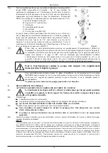
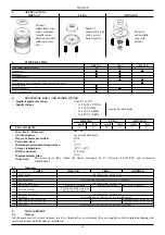
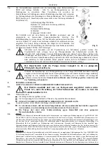
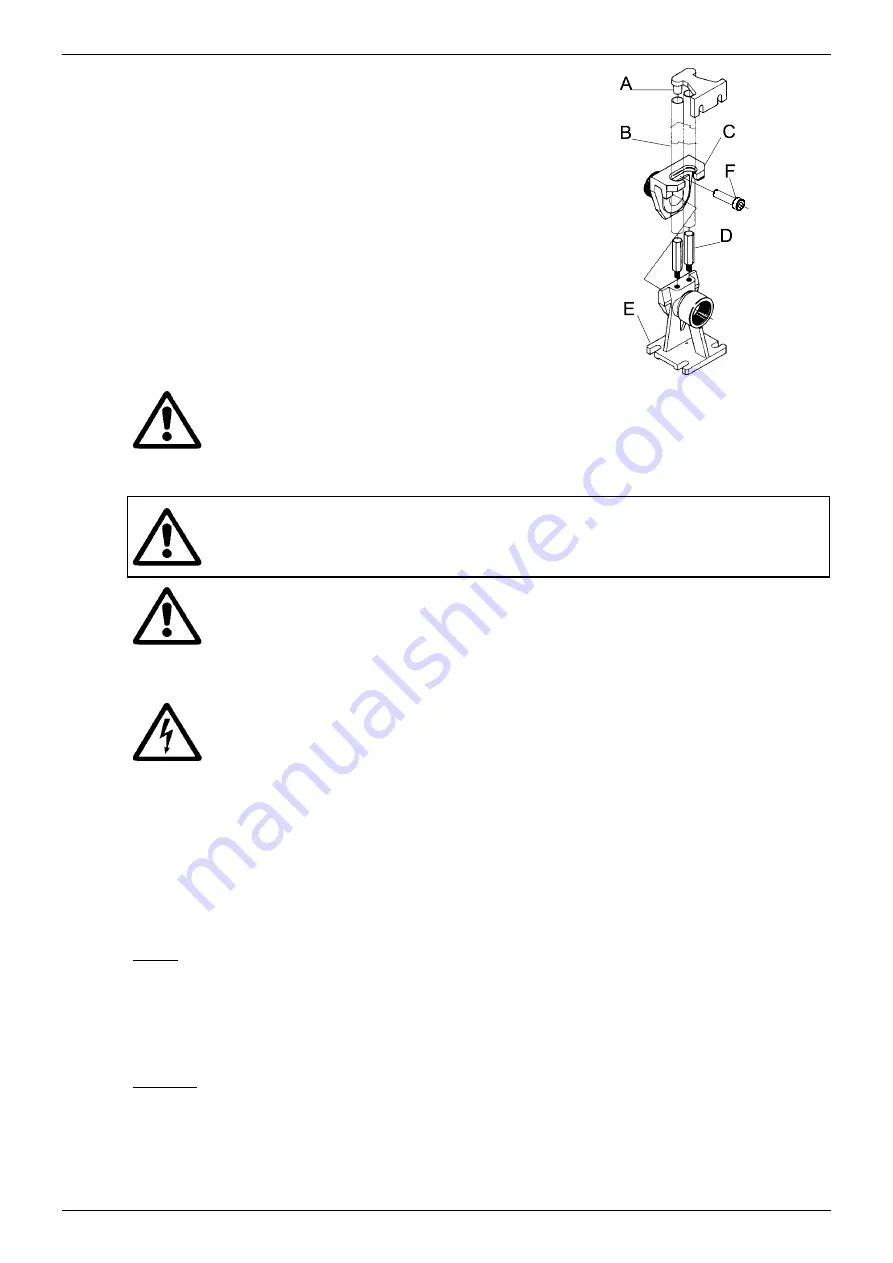
For fixed installations we advise the use of the lifting device DSD2
(available on request - fig. 2) to facilitate pump maintenance operations.
When fitted between the pump delivery aperture and the pipe, it avoids
having to remove the delivery pipe during maintenance jobs. The DSD2
device is composed of 5 parts:
A. Pipe anchoring bracket
B. 3/4" pipes (not supplied)
C. Slide
D. Pipe guide columns
E. Foot
F. Screw TCEI M10X35
The foot is positioned on the bottom of the tank and fixed with expansion
screws of suitable dimensions. The pipe guide bracket must be
positioned at the top of the well or borehole and inserted in the end of two
3/4" pipes (not supplied), which act as a slide. The two pipes connect the
bracket to the foot. Screw the slide onto the pump delivery aperture and
anchor it with the retaining screw TCEI M10X35.
(Fig. 2)
7.7.
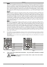
Particular care must be taken in positioning the floats. The command for starting the pump must be
given before the level of the liquid reaches the cover of the borehole. The command for stopping the
pump must be given before the level of the liquid uncovers the top of the pump (see drawings on page
99- Ref. A - minimum level for continuous duty). The float must never rest on the bottom of the
borehole or touch against the cover, if there is one. Care must also be taken to ensure that the float
does not catch on protruding parts or other obstacles in the borehole.
For continuous duty the pump must always be completely immersed in the
liquid to be pumped.
7.8.
Be very careful during installation or maintenance of the GRINDER pump as on the intake cover,
over the intake aperture, there is a very sharp grinding device which could cause serious problems if
you were to touch it with your hands during work.
Never put your hands under the pump when it is connected to the power mains
8. ELECTRICAL
CONNECTION
CAUTION! ALWAYS FOLLOW THE SAFETY REGULATIONS.
8.1.
The electrical connections must be made exclusively by skilled personnel (see
point 6.1) as required by the safety regulations in force in the country in which
the product is installed.
8.2.
Ensure that:
the system is correctly made;
the mains voltage is the same as the value shown on the data plate;
THERE IS THE POSSIBILITY OF MAKING A GOOD EARTH CONNECTION.
8.3.
Check accurately to ensure that the protections have been correctly installed.
Fixed pumping stations must always be provided with an automatic switch with an intervention
current of less than 30 mA.
The pump must not operate without overload protection and a suitable motor protector.
8.4.
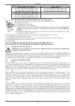
Depending on the pump to be installed, for correct installation one of the following electronic panels (supplied on
request) must be used:
ED 3 M
Electric control panel for the protection and automatic operation by float(s) of single-phase electropumps type DRENAG 1400
M et FEKA 1400 M. Supplied complete with knife switch for isolating the power supply line. Contains the capacitor, the
automatic magnetothermal switch for protection against overloads and short circuits with manual reset, the thermal protection
with manual reset for connection to the wires KK coming from the motor, the terminal board for connecting the electropump
and the float(s). Complete with terminals for connecting an alarm float and terminals for feeding an acoustic or luminous
remote alarm to warn when it has tripped. Provided with a MANUAL operation button. Internal transformer complete with
self-resetting protection against overloads and short circuits, cutting off the feeding voltage for three minutes.
ED 3 M Hs
Electric control panel for the protection and automatic operation by float(s) of single-phase electropumps type GRINDER 1400
M. Supplied complete with knife switch for isolating the power supply line. Contains the capacitors (one for increasing the
starting torque), the automatic magnetothermal switch for protection against overloads and short circuits with manual reset, the
thermal protection with manual reset for connection to the wires KK coming from the motor, the terminal board for connecting
the electropump and the float(s). Complete with terminals for connecting an alarm float and terminals for feeding an acoustic
or luminous remote alarm to warn when it has tripped. Provided with a MANUAL operation button. Internal transformer
complete with self-resetting protection against overloads and short circuits, cutting off the feeding voltage for three minutes.
Summary of Contents for DRENAG 1000-1200
Page 95: ...65 2 A B C D B C D 3 A B B 4 A B C A B C 5 A B C A B C...
Page 120: ...90 4 A B C A B C A A B C A B C...
Page 133: ...103 GRINDER...


