ENGLISH
23
10.2.
Checking and changing the grinding device on Grinder electropumps
If a gradual decrease of flow rate is noted, due presumably to possible clogging of the intake aperture, it is advisable to check
and, if necessary, change both the rotating part and the fixed part of the grinding device, as it may have lost its grinding
capacity.
Periodic checking of the grinding device may be made to coincide with scheduled maintenance of the seal oil level.
10.3.
Checking and changing the seal oil
10.3.1
Checking the seal oil
For good pump operation the oil must be checked about every 2000 working hours and changed at least once a year. Check the
oil with the pump in vertical position, unscrewing the cap provided (64) and ensuring that the oil level is just below the hole.
Top up if necessary.
10.3.2
Changing the seal oil
Unscrew the cap (64), drain the oil chamber with the pump in horizontal position (hole facing downwards) and collect the oil
in a container. If the oil contains particles of water or abrasive material (for example, sand) it is advisable to check the
condition of the mechanical seal (16) and change it if necessary.
Old oil must be disposed of in conformity with the laws in force.
Fill with new oil through the hole provided, with the pump in vertical position, using about 0.3 kg of non-foaming hydraulic
oil for DRENAG and GRINDER and about 0.4 kg for FEKA pumps.
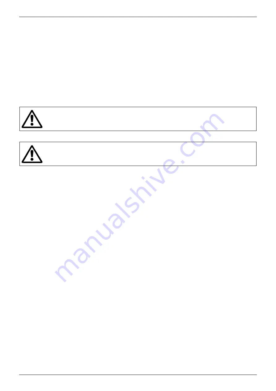
ATTENTION: The seal chamber must never be completely filled, but only up to the
level of the hole, to leave room for thermal expansion of the oil.
10.4.
Checking and changing the mechanical seal
10.4.1
Checking the mechanical seal
Check as described in paragraph 10.3.2 "Changing the seal oil".
10.4.2
Changing the mechanical seal
Once the impeller (4) has been dismantled, remove the spring and the centring disc of the rotating part of the mechanical seal
(16). Levering with two screwdrivers on the pump body, slip the rotating part of the mechanical seal (16) off the shaft (7),
taking care not to spoil the sliding faces. Repeat the operation to remove the fixed part of the mechanical seal (16), levering
on the seal's external diameter.
To fit the new mechanical seal, proceed as follows: the seat of the pump body containing the fixed part of the mechanical seal
(16) must be free from residue, scale, oxides, etc. Insert the fixed part of the mechanical seal, complete with gasket, in the seat
in the pump body (1), using a pad protected with plastic. The movement of the pad must be perfectly in line with the axis of
the part. To reassemble the rotating part of the mechanical seal (16), cap the end of the shaft with the tapered pin provided.
Slip the rotating part of the seal (16) onto the pin and press firmly with a special sleeve until the seal is securely fitted on the
shaft. Before carrying out this operation, always ensure that the contact surfaces of the seal are both perfectly clean. Fit the
spring and the centring disc.
10.5. Resetting
clearance
After a large number of working hours, for DRENAG and GRINDER pumps, it may be necessary to adjust the clearance
between the impeller (4) and the intake cover (35). In this case proceed as follows:
10.5.1 Drenag
Unscrew the three screws (136), remove the strainer cover (92) and the intake strainer (42). Slacken the three screws TCEI
M8 (93) and unscrew the three screws STEI M6 (135) by about 4 turns. Ensure that the intake cover (35) touches the impeller
(4). Then tighten the three screws STEI M6 (135) until they touch the pump body (1) and give them a final turn in a clockwise
direction to restore the correct distance between the impeller (4) and the intake cover (35). Tighten the three screws TCEI M8
(93), reposition the intake strainer (42) and the strainer cover (92) and secure with the screws TE M8 (136).
10.5.2 Grinder
Slacken the three screws TCEI M8 (93) and unscrew the three screws STEI M6 (135) by about 4 turns. Ensure that the intake
cover (35) touches the impeller (4). Then tighten the three screws STEI M6 (135) until they touch the pump body (1) and give
them a final turn in a clockwise direction to restore the correct distance between the impeller (4) and the intake cover (35).
Tighten the three screws TCEI M8 (93).
Summary of Contents for DRENAG 1000-1200
Page 95: ...65 2 A B C D B C D 3 A B B 4 A B C A B C 5 A B C A B C...
Page 120: ...90 4 A B C A B C A A B C A B C...
Page 133: ...103 GRINDER...


