


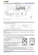


Instruction manual V 2.3
3
PWM 230 - PWM 400 - PWM 400/7.5
Instruction manual
TABLE OF CONTENTS
1
INTRODUCTION ........................................................................................................................................ 7
1.1
Applications ......................................................................................................................................... 8
1.2
Technical features ............................................................................................................................... 8
2
INSTALLATION ......................................................................................................................................... 9
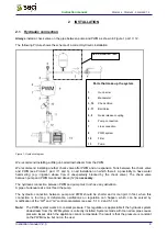
2.1
Hydraulic connection........................................................................................................................... 9
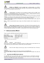
2.2
Electrical connection PWM 230 ........................................................................................................ 10
2.2.1
Connection to the PWM 230 power supply line......................................................................... 10
2.2.2
Electrical connection to the electro pump for PWM 230 device ................................................ 11
2.3
Electrical connection of PWM 400 and PWM 400/7.5 ...................................................................... 12
2.3.1
Connection of the PWM 400 – PWM400/7.5 to the power supply line...................................... 13
2.3.2
Electrical connection of the electro pump to PWM 400 – PWM400/7.5 devices....................... 13
2.4
Electrical connection of user inputs and outputs of PWM230 PWM400 PWM400/7.5..................... 14
2.5
Electrical connections for interconnection and exchange................................................................. 18
2.5.1
Electric wiring for interconnection of two PWM.......................................................................... 18
2.5.2
Electrical connections for wiring with “Da Vinci” controller board .............................................. 18
3
THE KEYPAD AND THE DISPLAY......................................................................................................... 20
3.1
Keys functionality .............................................................................................................................. 20
3.2
Display conventions .......................................................................................................................... 20
3.3
Meaning of the messages shown on the display .............................................................................. 21
4
START AND FIRST OPERATION........................................................................................................... 23
4.1
Start up operation.............................................................................................................................. 23
4.2
Typical installation ............................................................................................................................. 25
4.2.1
Installation with an electro pump ............................................................................................... 25
4.2.2
Installation with two electro pumps ............................................................................................ 25
4.2.3
Installation with 1, 2, 3 or 4 electro pumps and “Da Vinci” controller board .............................. 25
4.3
First installation troubleshooting........................................................................................................ 26
5
PARAMETER MEANINGS ...................................................................................................................... 27
5.1
Configurable parameters................................................................................................................... 27
5.1.1
User’s parameters (MODE & SET access keys) ....................................................................... 27
5.1.1.1
SP: Setting the set-point pressure...................................................................................... 27
5.1.2
Installer’s parameters (access keys MODE & SET & -) ............................................................ 27
5.1.2.1
rC: Setting the rated current of the electro pump ............................................................... 27
5.1.2.2
Fn: Setting the rated frequency .......................................................................................... 28
5.1.2.3
rt: Setting the direction of rotation....................................................................................... 28
5.1.2.4
od: Setting the operating mode of the PWM....................................................................... 28
5.1.2.5
rP: Setting the restart pressure drop .................................................................................. 29
5.1.2.6
Ad: Setting the interconnection address............................................................................. 29
5.1.2.6.1
Setting the address for booster sets composed by 2 PWM ........................................... 29
5.1.2.6.2
Setting address for connection to “Da Vinci” controller board ........................................ 30
5.1.2.7
Eb: Enable booster ............................................................................................................. 30
5.1.3
Technical assistance Displays and settings (access keys MODE & SET & +) ......................... 31
5.1.3.1
tB: Setting of reaction time of the water lack blockage....................................................... 31
5.1.3.2
GP: Setting the proportional coefficient of the PI ............................................................... 31
5.1.3.3
GI: Setting the integral coefficient of the PI ........................................................................ 31
5.1.3.4
FS: Setting the maximum rotation frequency of the electro pump ..................................... 31
5.1.3.5
FL: Setting the min. frequency............................................................................................ 32
5.1.3.6
Ft: Setting the low flow rate threshold ................................................................................ 32


