


Instruction manual V 2.3
9
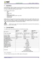
PWM 230 - PWM 400 - PWM 400/7.5
Instruction manual
2 INSTALLATION
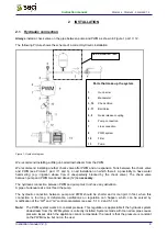
2.1 Hydraulic
connection
Always
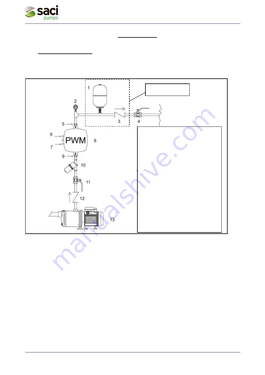
install a check valve on the pipe between pump and PWM as shown in Figure 1 part n° 12.
The following Picture shows the scheme of a correct Hydraulic installation.
Figure 1: Hydraulic diagram
We recommend installing a little gun barrel downstream from the PWM.
We recommend installing another check valve after PWM and an expansion Tank between the check valve
and PWM (see Picture 1 part n°1 and 3), on all Installation on which there’s a possibility to have water
hammering (e.g. irrigation whose flow is unexpectedly blocked by the check valve). The check valve
between pump and PWM mentioned above (12)
is necessary.
The hydraulic connection between PWM and pump must not have any derivation.
A pipe of adequate size must feed the pump.
The hydraulic connection between pump and PWM should be shorter and more rigid. In fact, when this
connection is too long or deformable, oscillations on regulation can happen, which can be solved by
modification of the “GP” and “GI” control parameters (see sec. 5.1.3.2 and 5.1.3.3)
Note:
The PWM system works at constant pressure. This regulation is appreciable if the hydraulic system
downstream from the PWM system is correctly installed. Systems made with too narrow pipes cause
pressure losses which the appliance cannot compensate; the result is that the pressure is constant
on the PWM device but not on the user.
See installation note
Parts that make up the system
1
Gun
barrel
2
Manometer
3, 12
Check
Valve
4, 11
Ball
Valve
5, 9
Quick
release
coupling
6
Pump
connection
7
Line
connection
8
PWM
system
10
Filter
13
Pump


