


Instruction manual V 2.3
18
PWM 230 - PWM 400 - PWM 400/7.5
Instruction manual
2.5 Electrical
connections
for interconnection and exchange
Each PWM has a communication port through which it can be connected by means of a special cable, to
another PWM or to a compatible controller board.
WARNING
:
When interconnection cable’s length exceeds 1m, usage of a shielded cable with braid
connected to earth (central pin number 2) is recommended on both devices.
2.5.1
Electric wiring for interconnection of two PWM
Two PWM devices may operate in a synchronized way (see sec. 5.1.2.6 “Ad: Setting the interconnection
address", 5.1.2.6.1 “Setting the address for booster sets composed by 2 PWM”, 5.1.2.7 "Eb: Enable booster"
and 5.1.3.7 "CM: Role exchange policy in booster sets").
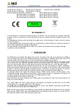
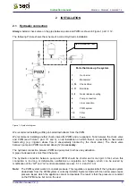
To use this functionality, two devices must be wired with a three-pole cable trough the terminal block J9, as
illustrated on Figure 13.
Figure 13: Wiring diagram for two PWM in exchange
2.5.2
Electrical connections for wiring with “Da Vinci” controller board
One or more PWMs can be wired to the “Da Vinci” controller board that monitors the system, controls and
manages the PWM’s operation (see instruction manual of “Da Vinci” controller board).
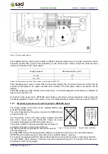
Two devices are wired by means of a three-pole cable trough the terminal block J9 as illustrated on Figure
14
.
The three PWM Terminals are wired to the controller board as shown on Table 7.
PWM 1 Connection
PWM 2 Connection
PWM 3 Connection
PWM 4 Connection
PWM terminal
Controller board
terminal
PWM terminal
Controller board
terminal
PWM terminal
Controller board
terminal
PWM terminal
Controller board
terminal
1
B1 -
1
B2 -
1
B3 -
1
B4 -
2 SH 2 SH 2 SH 2 SH
3
B1 +
3
B2 +
3
B3 +
3
B4 +
Table 7: Pin out of cable used for communication between PWM and "Da Vinci" controller board
PWM 1
PWM 2


