background image


Instruction manual V 2.3 


39

PWM 230 - PWM 400 - PWM 400/7.5 

Instruction manual


The following table shows the procedures performed by PWM when different error conditions occur: 


Automatic reset of error conditions 

Display indications 

Description 

Sequence of automatic reset 

BL 

Blockage due to lack of 
water 

- One attempt every 10 min. for a total of 6 attempts 
- One attempt every 1 hour for a total of 24 attempts 
- One attempt every 24 hours for a total of 30 attempts 

LP 

Blockage due to low supply 
voltage (lower than 184V for 
PWM 230 and 320V for 
PWM 400) 

- Recovery happens when line voltage returns to be 
higher than 184 V for PWM 230 and than 320 V for 
PWM 400 

HP 

Blockage due to high supply 
voltage (higher than 264V 
for PWM 230 and 457V for 
PWM 400) 

- Recovery happens when voltage returns to be lower 

than 264 V for PWM 230 and lower than 457 V for 
PWM 400 

ot 

Blockage due to overheating 
of the power stages (tE > 
100°C) 

- Recovery happens when the power stages’ 

temperature falls below 85°C  

ob 

Blockage due to overheating 
of the printed circuit 
(bt > 120°C) 

- Recovery happens when the printed circuit’s 

temperature falls below 100°C 

oC 

Blockage due to overcurrent 
of the pump 

- One attempt every 10 min. for a total of 6 attempts 

oF 

Blockage due to overcurrent 
in the output stages 

- One attempt every 10 min. for a total of 6 attempts 


Table 14: Automatic reset of error conditions 


SWITCHING TO MANUAL MODE 


A greater flexibility is achievable by using the system in manual mode. In this operating mode the PWM 
performs no pressure control action and the user can force it to perform some actions, according to the 
possibilities listed in this chapter. 

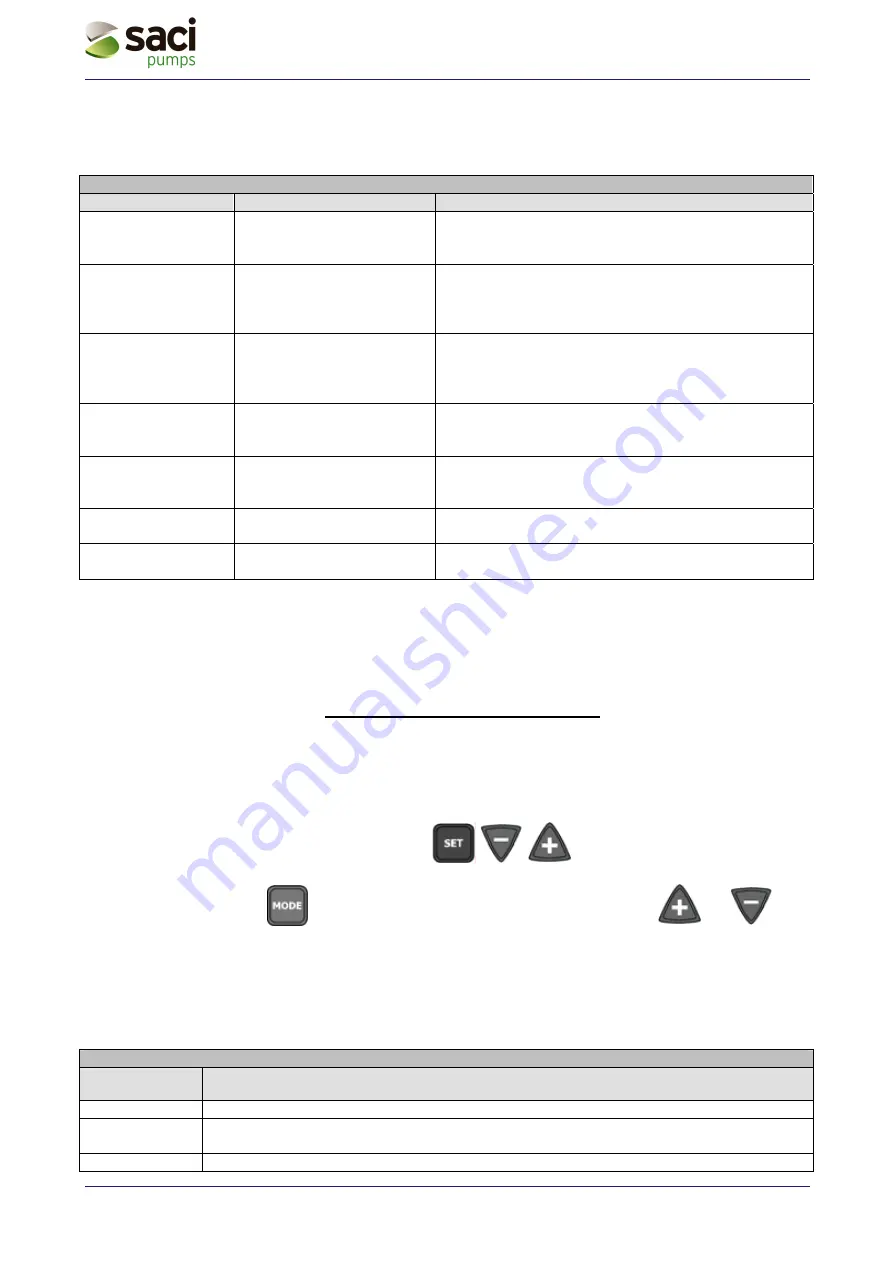
To access to this operating mode, hold down the 


 keys simultaneously for at least 5 

seconds. Activation of manual mode is signalled by a blinking display. 

In this operating mode the 

 key allows to scroll through all parameters and the 

 and

 keys 

increase and decrease the modifiable parameters. 
The functions of the keys and their combinations are summarized in Table 15 and explained in the sections 
that follow.  
 

Warning

: In this mode all controls and protection systems of the PWM are disabled and any device 

connected to the PWM (PWM or controller board) cannot control regulation. 
 

Use of the keys. 

Pressed keys 

Action 

“SET” & “-” & “+“  Press them together until the display shows “MA” (5 sec.) 

“+” 

Increases the parameter’s value if it does not yet equal the maximum allowed one (only 
frequency and rotation direction of the pump) 

“-“ 

Decreases the parameter’s value if it does not yet equal the minimum allowed one (only 

Summary of Contents for EASY VARIO PWM230

Page 1: ...BOMBAS SACI S A MANUAL DE USO Y MANTENIMIENTO AMPLIACION MANUAL DE FUNCIONAMIENTO Y MANTENIMIENTO DE EQUIPOS DE PRESI N CON VARIADOR DE FRECUENCIA EASY VARIO SYSTEM BADALONA LA CORU A portada easy var...

Page 2: ...pretaremos a la vez las teclas MODE SET y MENOS en el cambio de men pulsaremos MODE hasta visualizar el par metro rt y con las teclas cambiamos el sentido de rotaci n si es necesario Para configurar l...

Page 3: ...ente integral del PI 10 6 1 3 4 FS Configuraci n de la frecuencia m xima de rotaci n valor preconfigurado 50Hz 10 6 1 3 5 dP Configuraci n del diferencial de presi n con flujos bajos valor preconfigur...

Page 4: ...a la l nea de alimentaci n PWM 230 3basic Conexi n de entrada 220V 240V 50Hz nominales monof sica Para versiones sin cables la l nea debe conectarse al borne J2 de 3 v as con indicaci n LINE y flecha...

Page 5: ...motor el ctrico de la electrobomba en estrella correspondiente al uso del PWM230 3 basic puede provocar la aver a del mismo motor La conexi n entre el PWM 230 3 Basic y la electrobomba se efect a con...

Page 6: ...normal de visualizaci n P lselo para disminuir el par metro actual modificable Cada vez que se pulsa el valor de la magnitud se visualiza durante 6 segundos como m nimo despu s aparece el identificad...

Page 7: ...n SET para colocarse en el men de visualizaci n normal en la pantalla aparece Go o Sb salvo que no hayan intervenido condiciones de error o de bloqueo Abra un elemento de servicio y observe la frecue...

Page 8: ...zaci n de la temperatura de los terminales de potencia C GS Visualiza el estado de funcionamiento FF Visualizaci n del historial de errores y bloqueos Acceso a la modalidad manual botones SET 5 segund...

Page 9: ...valores rP indica en metros la disminuci n de presi n que provoca el arranque de la bomba v ase p rrafo 6 1 2 4 dP indica en metros la disminuci n de presi n deseada respecto de SP con flujos bajos v...

Page 10: ...lo cambiando este par metro Si no fuera posible observar el sentido de rotaci n del motor proceda de la siguiente manera o Abra un elemento de servicio y observe la frecuencia par metro Fr con el bot...

Page 11: ...esta lenta del sistema pueden compensarse aumentando el valor de GI Por el contrario al producirse vibraciones en la presi n oscilaciones de presi n muy r pidas alrededor del valor de setpoint puede e...

Page 12: ...abilitada si el PWM mide una temperatura muy baja con riesgo de congelaci n comienza autom ticamente a hacer funcionar la electrobomba a bajos n meros de revoluciones Mantener el agua en movimiento re...

Page 13: ...entre las fases del borne de salida SC se puede intentar salir de las condiciones de error pulsando simult neamente los botones y Si la condici n de error persiste hay que eliminar el problema que ha...

Page 14: ...namiento y algunas condiciones de bloqueo el sistema intenta reajustar autom ticamente la electrobomba El sistema de ayuda de reajuste concierne a bL Bloqueo por falta de agua ot Bloqueo por recalenta...

Page 15: ...es pulsados Acci n SET P lselos juntos durante alg n instante hasta que en la pantalla aparezca MA Aumenta el par metro configurable s lo frecuencia y sentido de rotaci n Disminuye el par metro config...

Page 16: ...bares tb Tiempo de bloqueo por falta de agua 10 s GP Ganancia del coeficiente proporcional 1 0 para PWM230 GI Ganancia del coeficiente integral 1 0 para PWM230 FS Frecuencia m xima de rotaci n 50 dP D...

Page 17: ...Instruction manual PWM230 PWM400 PWM400 7 5 Ver 2 3 EASY VARIO...

Page 18: ...with an electro pump 25 4 2 2 Installation with two electro pumps 25 4 2 3 Installation with 1 2 3 or 4 electro pumps and Da Vinci controller board 25 4 3 First installation troubleshooting 26 5 PARAM...

Page 19: ...he software with which the appliance is equipped 35 5 2 2 MONITOR menu accessed by SET keys 36 5 2 2 1 UF Display of the flow 36 5 2 2 2 ZF Display of zero flow 36 5 2 2 3 FM Display of the maximum ro...

Page 20: ...queue 37 Table 13 Error conditions 37 Table 14 Automatic reset of error conditions 39 Table 15 Keys usage in manual mode 40 Table 16 Factory settings 43 Table 17 Energy saving 44 FIGURES INDEX Figure...

Page 21: ...heir knowledge of the relevant standards regulations and accident prevention rules and working conditions have been authorized by the person responsible for safety of the plant to perform all the appr...

Page 22: ...nd the PWM manages the pump according to the user s needs to do this particular algorithms are used to control frequency of rotation The PWM system turns on the pump when there is a water demand and t...

Page 23: ...d with feed liquid inflammable fluid by products of the hydrocarbons aggressive corrosive or viscous fluids 1 2 Technical features The following chart shows all technical features of the PWM series sy...

Page 24: ...The hydraulic connection between PWM and pump must not have any derivation A pipe of adequate size must feed the pump The hydraulic connection between pump and PWM should be shorter and more rigid In...

Page 25: ...top the flow valve thus jeopardizing correct operation of the system In case that the PWM is installed on a pipeline through which foreign bodies e g gravel in case of submersibles pumps can transit i...

Page 26: ...egulation in force in the country of use The total grounding resistance must not exceed 100 Ohm 2 2 2 Electrical connection to the electro pump for PWM 230 device The supply voltage of the motor of th...

Page 27: ...PWM 400 7 5 Power supply to the PWM 400 and PWM 400 7 5 devices should meet the following requirements Rated voltage 400 V 10 20 Minimum absolute voltage 320 V 400 V 20 Maximum absolute voltage 457 V...

Page 28: ...n can be reduced proportionally to the power decrease for example if the total power halves the section will be halved PWM 400 and PWM400 7 5 already provide internal current protections If a thermal...

Page 29: ...pliance Wrong connection of the power supply line on output terminals intended for the load may cause irremediable damage to the whole appliance Once the electric and hydraulic connections are complet...

Page 30: ...Figure 10 Example application of user outputs Potential free contact for alarm signalling Potential free contact for running pump signalling 8 9 10 11 Example application of o1 and o2 outputs o1 o2 8...

Page 31: ...be driven with any polarity with respect to their own earth return and they work with alternate or direct current Correct operation is guaranteed if input voltages comply with the following requireme...

Page 32: ...float switch for setting details see sec 5 1 3 9 1 I1 Setting function of input 1 external float Driving with potential free contacts Driving with external Voltage IN 3 usage example When IN 3 is enab...

Page 33: ...evices must be wired with a three pole cable trough the terminal block J9 as illustrated on Figure 13 Figure 13 Wiring diagram for two PWM in exchange 2 5 2 Electrical connections for wiring with Da V...

Page 34: ...am for connection of PWM to the Da Vinci controller board Note For PWM systems wired and configured to work with Da Vinci controller board operation of input 2 is disabled see sec 5 1 3 9 2 a new menu...

Page 35: ...displayed for at least 5 seconds Thereafter the parameter name appears Note When or is pressed the selected quantity will be changed and immediately saved in permanent memory EEPROM Hence the paramete...

Page 36: ...d current of the electro pump A Fn Setting the rated frequency of rotation of the electro pump Hz rt Setting the direction of rotation duplicated in manual mode od Setting the PWM operating mode rP Se...

Page 37: ...2 function DISPLAY keys for 2 sec UF Display of the flow duplicated in manual mode ZF Display of zero flow duplicated in manual mode FM Display of the max rotation frequency Hz tE Display of the power...

Page 38: ...PWM 400 7 5 the motor must be configured to operate with a 400V three phase system normally with a star wiring if power is less than 5 5 KW with a delta wiring for higher power The rated current para...

Page 39: ...display menu Go or Sb is displayed provided that no errors or lock conditions are present Enter manual mode menu by holding the keys simultaneously pressed until MA appears on display see chap 7 Star...

Page 40: ...ctor see sec 2 5 1 Power the PWM Follow steps a b c of sec 4 1with each device rC Fn rt On one of the two devices press for 5 seconds then press the key multiple times until Ad is displayed and with t...

Page 41: ...osing to the impeller or the motor s motion Check the phases connection of the motor OC 1 Wrong setting of the pump current rC 2 Pump blocked 1 Set rC with the current related to the type of wiring st...

Page 42: ...measured in bar with respect to SP that causes the pump to start see sec 5 1 2 5 Example SP 3 0 bar rP 0 5 bar During normal operation the system will be pressurized at 3 0 bar The electro pump will r...

Page 43: ...side the above mentioned range A wrong setting of the rated frequency can damage the electro pump Note each modification of Fn is interpreted as a system change hence FS FL and FP will automatically t...

Page 44: ...ith the following meanings Communication is disabled 1 the board acts as secondary PWM 2 the board acts as primary PWM 3 communication with the controller board 5 1 2 6 1 Setting the address for boost...

Page 45: ...isplay while showing Go or Sb When PWM is operating under the controller board s supervision the latter reads all parameters from the PWM and controls PWM operation Managing of booster sets is done fr...

Page 46: ...the ones set by the factory For most systems the factory default values of GP and GI parameters are the optimal ones If there are some regulation problems these settings may be modified 5 1 3 3 GI Se...

Page 47: ...eases the booster machine is turned off while the leader machine continues regulating CM 01 The primary and secondary PWM act as leader or as booster alternatively The roles are exchanged each time th...

Page 48: ...be at 0 not energized for at least 30 sec before the system unlocks i1 02 Lack of water from external float NC IN1 00 not energized input Alarm F1 on display and system lock lack of water from extern...

Page 49: ...splayed i3 02 General enable NC IN3 0 not energized input System disabled F3 is displayed IN3 1 energized input System disabled GO or Sb is displayed i3 03 General enable NO This case is identical to...

Page 50: ...Display only parameters From normal operation status the following quantities can be displayed by pressing the MODE key 5 2 1 User s parameters accessed by the MODE key From normal operation status S...

Page 51: ...nd stop at the oldest fault whereas by pressing the key you can go forward in history and stop at the most recent fault The decimal point identifies the last fault that occurred in chronological order...

Page 52: ...rcuit alarm bt 100 C Table 12 Warning on the fault history queue Error conditions Error and status conditions Display indications Description bL Blockage due to lack of water bP Blockage due to discon...

Page 53: ...on in general Once these checks have been made you can try to recover from the error by simultaneously pressing the and keys anyway this will have no effect until 10 seconds have elapsed from the mome...

Page 54: ...p One attempt every 10 min for a total of 6 attempts oF Blockage due to overcurrent in the output stages One attempt every 10 min for a total of 6 attempts Table 14 Automatic reset of error conditions...

Page 55: ...ditions 7 1 Parameters in manual mode 7 1 1 FP test frequency setting The test frequency in Hz it is displayed and can be modified by pressing the and keys The default value is Fn 20 and values cannot...

Page 56: ...f the pressure again The right value of rt is obtained when the pressure is maximized 7 1 5 UF display of the flow 7 1 6 ZF display of Zero Flow 7 2 Controls When PWM is in manual mode it is always po...

Page 57: ...erating mode but if the pump is running pressure of the key only stops the pump 7 2 3 Direction of rotation reversal By simultaneous pressure of the keys for at least 2 seconds the pump s rotating dir...

Page 58: ...memory are copied on EEPROM and verified After having set all parameters PWM goes back to normal operation Name Description Factory parameters SP Set point pressure 3 0 bar rC Rated current of the el...

Page 59: ...ow demand Test performed with a 1 5 KW electro pump and prevalence set to 30 mH2O Flow l min Statistic use of flow Direct insertion consumption KW Consumption with PWM KW Power difference KW Energy sa...

Reviews: