8 - 8
176.12
.A03
Revision 01 Date 14.11.2001
8
MAINTENANCE
14
16
10
T0457
9
10
14
11
12
13
T0466
FIGURE 8.1.2.1/E
FIGURE 8.1.2.1/D
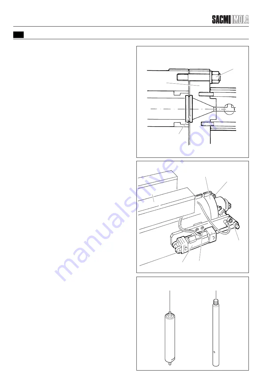
To remove the auger, proceed as directed below,
depending on the type of extruder installed:
20 kg/h extruder
- Remove the guard that protects the threaded hole
found on top of the auger. The guard has left-hand
threading. To unscrew, tap along its periphery with a
copper rod. Gently retighten.
- Screw the tool (20) in the hole left free by the guard and
remove the extruder auger.
40 kg/h extruder
- Remove the guard (17) located behind the reduction
gear unit aligned with the extruder.
- Insert the tool (21) provided to push the extrusion
auger forward so that it can be removed from the
extrusion head.
If the tool is not long enough, adequate spacers have
to be provided.
When the auger is approx. 10 cm out, the operation
can be facilitated by using your hands.
Cleaning the auger and filter
- Thoroughly clean the auger with hand tools, removing
any resin present. If the surface of the auger is dark
and opaque, polish it with a brush and abrasive paste.
As an alternative, the auger can be soaked in a normal
paint diluent for 8 - 10 hours to clean it. For this purpose
a tube capable of holding the auger should be used. A
plug should be sealed to an end of the tube to close it.
Once all the resin has been removed, the auger will still
be dark therefore it needs to be polished.
- Clean and polish the inside of the cylinder with a fine
bristle brush.
- Clean and polish the head’s duct.
- Thoroughly clean the filter (16). Replace it if worn. Use
a drill with a 1.75 mm Ø bit to open the filter holes.
To reassemble, perform the same operations in reverse
order.
The nuts (14) are to be tightened with a torque wrench
set to 14 kgm.
Before restarting the machine, make the adjustments
described in the “EXTRUDER ADJUSTMENTS”
paragraph.
FIGURE 8.1.2.1/E
T2701
20
21
Summary of Contents for PMV 224
Page 2: ...TABLE OF CONTENTS 176 12 A03 0 2 Revision 01 Date 14 11 2001 ...
Page 4: ...TABLE OF CONTENTS 176 12 A03 0 4 Revision 01 Date 14 11 2001 ...
Page 34: ...2 22 176 12 A03 Revision 01 Date 14 11 2001 2 MAIN FEATURES ...
Page 42: ...3 8 176 12 A03 Revision 01 Date 14 11 2001 SAFETY EQUIPMENT AND PRECAUTIONS 3 ...
Page 64: ...5 4 5 START UP 176 12 A03 Revision 01 Date 14 11 2001 ...
Page 70: ...6 6 176 12 A03 Revision 01 Date 14 11 2001 6 OPERATING INSTRUCTIONS ...
Page 126: ...8 30 176 12 A03 Revision 01 Date 14 11 2001 8 MAINTENANCE ...
Page 128: ...9 2 176 12 A03 Revision 01 Date 14 11 2001 9 DECOMMISSIONING ...


