8 - 10
176.12
.A03
Revision 01 Date 14.11.2001
8
MAINTENANCE
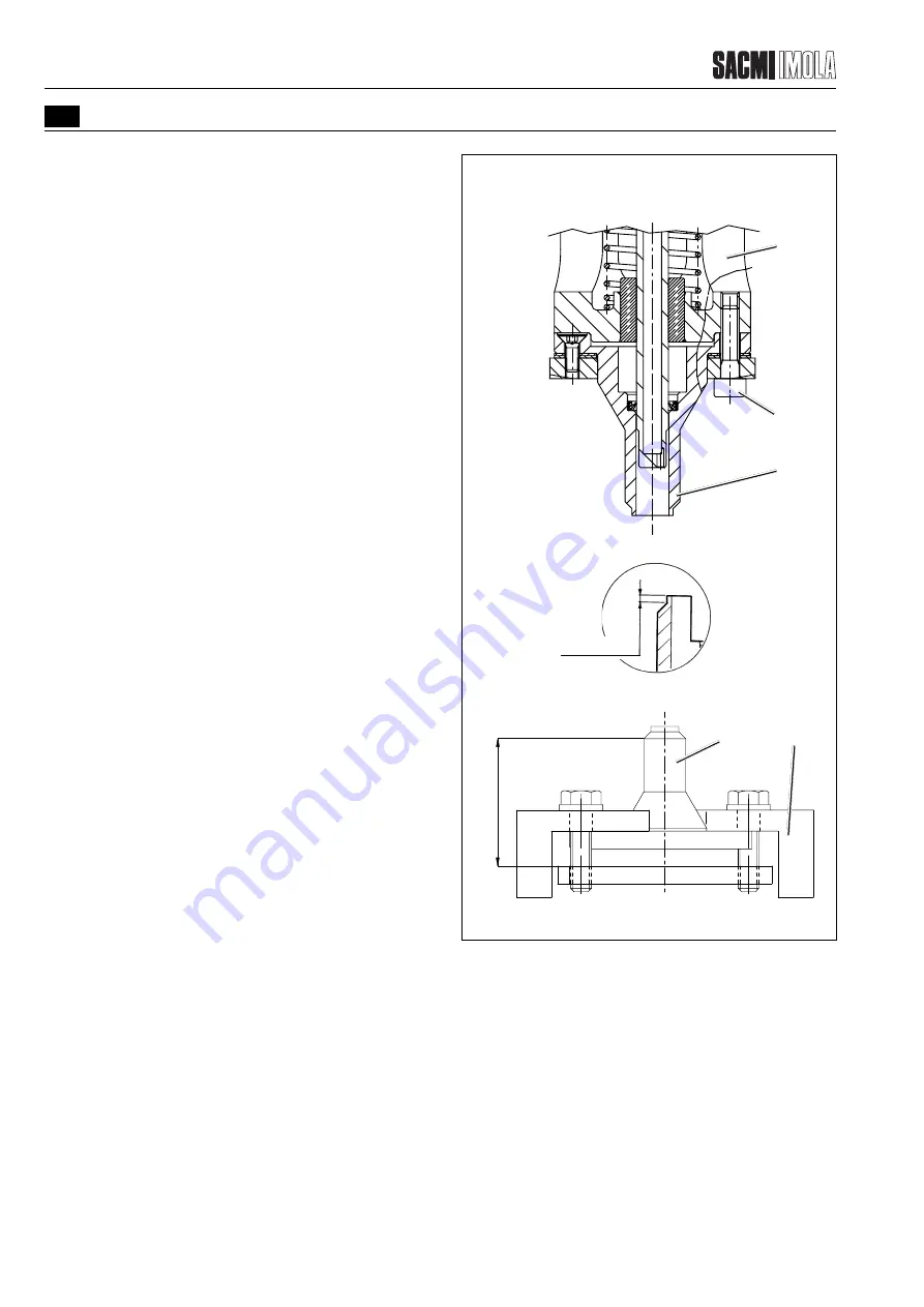
Aluminium cutters
Proceed as directed below:
- Remove the cutter (1) from the assembly (3) by
loosening the screws (5).
- Place the cutter (1) in the fixture (Y) as indicated in the
diagram. (This fixture can be placed on a magnetic
surface or in a vice).
- Grind the cutters by removing the minimum amount of
material necessary so that cutting can be performed
properly. The result should be that value A is the same
for all the cutters and value B should be within the
values indicated in the diagram.
- Remove the cutter (1) from the fixture and put it back
into place on the assembly (3).
B (0.2-1.5)
T2505
T0460
T2435
FIGURE 8.1.2.2/B - ALUMINIUM CUTTERS
3
5
1
A (30
±
0.025
)
X
1
Summary of Contents for PMV 224
Page 2: ...TABLE OF CONTENTS 176 12 A03 0 2 Revision 01 Date 14 11 2001 ...
Page 4: ...TABLE OF CONTENTS 176 12 A03 0 4 Revision 01 Date 14 11 2001 ...
Page 34: ...2 22 176 12 A03 Revision 01 Date 14 11 2001 2 MAIN FEATURES ...
Page 42: ...3 8 176 12 A03 Revision 01 Date 14 11 2001 SAFETY EQUIPMENT AND PRECAUTIONS 3 ...
Page 64: ...5 4 5 START UP 176 12 A03 Revision 01 Date 14 11 2001 ...
Page 70: ...6 6 176 12 A03 Revision 01 Date 14 11 2001 6 OPERATING INSTRUCTIONS ...
Page 126: ...8 30 176 12 A03 Revision 01 Date 14 11 2001 8 MAINTENANCE ...
Page 128: ...9 2 176 12 A03 Revision 01 Date 14 11 2001 9 DECOMMISSIONING ...


