8 - 13
176.12
.A03
Revision 01 Date 14.11.2001
MAINTENANCE
8
8.1.2.4
Disassembling the forming plunger
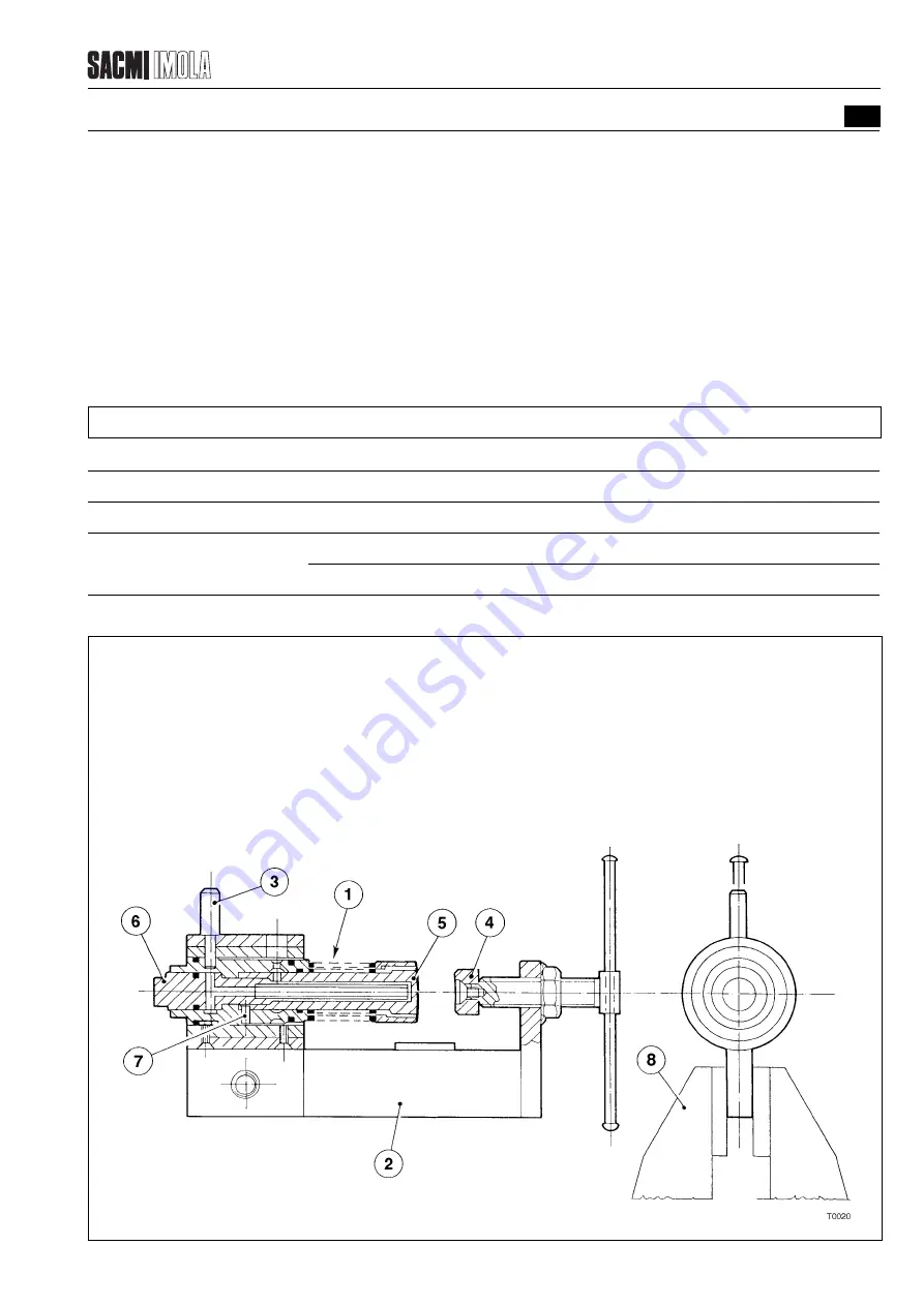
After removing the forming plunger from the drum , proceed as follows to disassemble it:
- Place the forming plunger (1) in the fixture (2).
- Insert the pin (3) in the reference hole in the plunger.
- Place the fixture in a vice (8) as shown in the diagram.
- Bring the jaw (4) into contact with the central plunger (5).
- Loosen the screw (6).
- Loosen the jaw (4).
At this point the components are loose and can be disassembled. To install, proceed in the reverse order making sure
that the cavity in the central plunger (5) coincides with the reference pin (7).
NOTE: The screw (6) must be tightened with a torque wrench set as indicated in the chart below.
Machine
Thread diameter of the plunger fixing screws
Tightening torque
PMV224
M12x1
3.5 daNm
PMV238
M16x1
10 daNm
M20x1
15 daNm
FIGURE 8.1.2.4 - DISASSEMBLING THE FORMING PLUNGER
1
Forming plunger
2
Fixture
3
Fixture reference pin
4
Jaw
5
Central plunger
6
Plunger set screw
7
Plunger reference pin
8
Bench vice
Summary of Contents for PMV 224
Page 2: ...TABLE OF CONTENTS 176 12 A03 0 2 Revision 01 Date 14 11 2001 ...
Page 4: ...TABLE OF CONTENTS 176 12 A03 0 4 Revision 01 Date 14 11 2001 ...
Page 34: ...2 22 176 12 A03 Revision 01 Date 14 11 2001 2 MAIN FEATURES ...
Page 42: ...3 8 176 12 A03 Revision 01 Date 14 11 2001 SAFETY EQUIPMENT AND PRECAUTIONS 3 ...
Page 64: ...5 4 5 START UP 176 12 A03 Revision 01 Date 14 11 2001 ...
Page 70: ...6 6 176 12 A03 Revision 01 Date 14 11 2001 6 OPERATING INSTRUCTIONS ...
Page 126: ...8 30 176 12 A03 Revision 01 Date 14 11 2001 8 MAINTENANCE ...
Page 128: ...9 2 176 12 A03 Revision 01 Date 14 11 2001 9 DECOMMISSIONING ...


