2 - 8
176.12
.A03
Revision 01 Date 14.11.2001
2
MAIN FEATURES
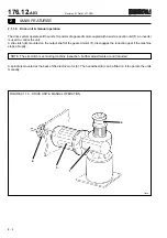
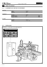
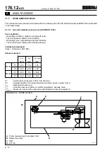
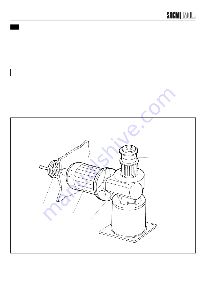
FIGURE 2.1.1.9 - DRIVE UNIT & MANUAL OPERATION
T0448
•
•
•
1
2
3
4
•
2.1.1.9
Drive unit & manual operation
The drive system operates all the units. It consists of a geared motor coupled with a worm reduction unit (1). An inverter
is used to control the unit.
A slip clutch (2), mounted on the output shaft of the geared motor (1), disengages the reduction gear if the machine
stops abruptly.
NOTE: The slip clutch is set during machine inspection. Further adjustments are not required.
A spindle is mounted at the back of the electric motor (3). The handwheel (4) can be fitted on it to operate the units
manually.
Summary of Contents for PMV 224
Page 2: ...TABLE OF CONTENTS 176 12 A03 0 2 Revision 01 Date 14 11 2001 ...
Page 4: ...TABLE OF CONTENTS 176 12 A03 0 4 Revision 01 Date 14 11 2001 ...
Page 34: ...2 22 176 12 A03 Revision 01 Date 14 11 2001 2 MAIN FEATURES ...
Page 42: ...3 8 176 12 A03 Revision 01 Date 14 11 2001 SAFETY EQUIPMENT AND PRECAUTIONS 3 ...
Page 64: ...5 4 5 START UP 176 12 A03 Revision 01 Date 14 11 2001 ...
Page 70: ...6 6 176 12 A03 Revision 01 Date 14 11 2001 6 OPERATING INSTRUCTIONS ...
Page 126: ...8 30 176 12 A03 Revision 01 Date 14 11 2001 8 MAINTENANCE ...
Page 128: ...9 2 176 12 A03 Revision 01 Date 14 11 2001 9 DECOMMISSIONING ...


