3 - 2
176.12
.A03
Revision 01 Date 14.11.2001
SAFETY EQUIPMENT AND PRECAUTIONS
3
3.1.2.4
Emergency stop buttons
Emergency stop buttons on board the machine
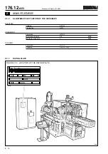
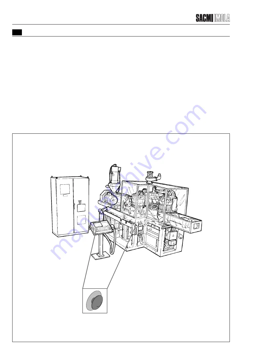
These are located in the positions indicated in the illustration below.
- Operation: manual
- Action: the drive system and machine motors, except those for the vacuum and suction pumps (required to transport
the product) stop immediately. Power to the auxiliary electric system and solenoid valve control system is cut off.
- Reset: from control panel, turn the button to release it.
Emergency stop button on the control panel
This is located on the control panel in the position indicated in the illustration.
- Operation: manual
- Action: the drive system and machine motors, except those for the vacuum and suction pumps (required to transport
the product) stop immediately. Power to the auxiliary electric system and solenoid valve control system is cut off.
- Reset: from control panel, turn the button to release it.
FIGURE 3.1.2.4 - LOCATION OF THE EMERGENCY STOP BUTTONS
T2452
Summary of Contents for PMV 224
Page 2: ...TABLE OF CONTENTS 176 12 A03 0 2 Revision 01 Date 14 11 2001 ...
Page 4: ...TABLE OF CONTENTS 176 12 A03 0 4 Revision 01 Date 14 11 2001 ...
Page 34: ...2 22 176 12 A03 Revision 01 Date 14 11 2001 2 MAIN FEATURES ...
Page 42: ...3 8 176 12 A03 Revision 01 Date 14 11 2001 SAFETY EQUIPMENT AND PRECAUTIONS 3 ...
Page 64: ...5 4 5 START UP 176 12 A03 Revision 01 Date 14 11 2001 ...
Page 70: ...6 6 176 12 A03 Revision 01 Date 14 11 2001 6 OPERATING INSTRUCTIONS ...
Page 126: ...8 30 176 12 A03 Revision 01 Date 14 11 2001 8 MAINTENANCE ...
Page 128: ...9 2 176 12 A03 Revision 01 Date 14 11 2001 9 DECOMMISSIONING ...


