4 - 9
176.12
.A03
Revision 01 Date 14.11.2001
INSTALLATION
4
4.3
CONNECTIONS
4.3.1
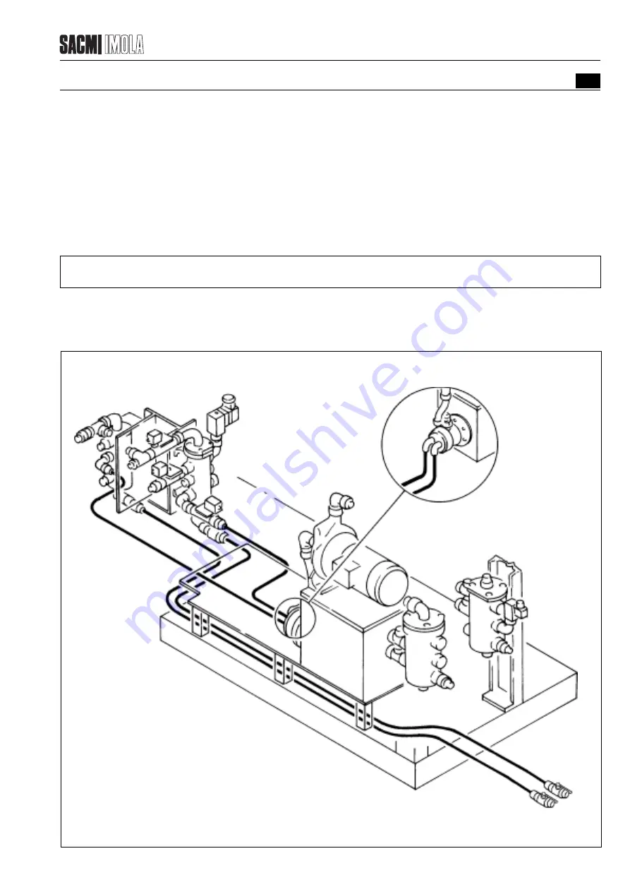
CONNECTING THE HOSES FOR THE COOLING SYSTEM
4.3.1.1
Hoses for joining the heat-exchanger to the auxiliary circuit tank
The delivery and return hoses (2M & 2R respectively), which are attached to the heat-exchanger of the tank (A), lead
to the extruder base and must be connected to the delivery and return manifolds (M & R respectively).
4.3.1.2
Hoses for joining the chiller to the manifolds (M & R)
The delivery and return hoses (3M & 3R respectively), which run from the chiller, have to be connected to the delivery
and return manifolds (M & R respectively) as shown in the diagram.
NOTE:
These connections are to be made by the customer.
2R
3R
3M
2M
A
2R
2M
3M
3R
Chiller
T2481
FIGURE 4.3.1 - CONNECTING THE HOSES FOR THE COOLING SYSTEM
Summary of Contents for PMV 224
Page 2: ...TABLE OF CONTENTS 176 12 A03 0 2 Revision 01 Date 14 11 2001 ...
Page 4: ...TABLE OF CONTENTS 176 12 A03 0 4 Revision 01 Date 14 11 2001 ...
Page 34: ...2 22 176 12 A03 Revision 01 Date 14 11 2001 2 MAIN FEATURES ...
Page 42: ...3 8 176 12 A03 Revision 01 Date 14 11 2001 SAFETY EQUIPMENT AND PRECAUTIONS 3 ...
Page 64: ...5 4 5 START UP 176 12 A03 Revision 01 Date 14 11 2001 ...
Page 70: ...6 6 176 12 A03 Revision 01 Date 14 11 2001 6 OPERATING INSTRUCTIONS ...
Page 126: ...8 30 176 12 A03 Revision 01 Date 14 11 2001 8 MAINTENANCE ...
Page 128: ...9 2 176 12 A03 Revision 01 Date 14 11 2001 9 DECOMMISSIONING ...


