4 - 11
176.12
.A03
Revision 01 Date 14.11.2001
INSTALLATION
4
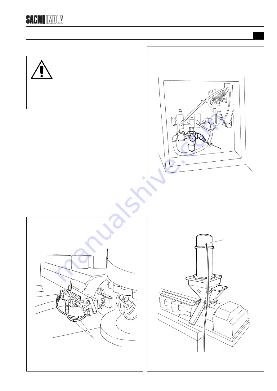
FIGURE 4.3.2.2 - PLASTIC COMPOUND FEEDER
T0391
B
4.3.2
CONNECTING THE PNEUMATIC SYSTEM
E0004P
IMPORTANT!
The machine’s pneumatic unit must be connected to
the mains air supply by observing all regulations
currently in force in the country where the machine is
installed.
4.3.2.1
Pneumatic unit
Connect a hose with internal diameter as indicated in the
specifications paragraph running from the compressed air
mains supply to the fitting (A).
4.3.2.2
Plastic compound feeder
- Use the hose (B) (6-8 mm dia.) to connect the plastic
compound feeder (if provided) to the point shown in the
figure.
4.3.2.3
Extruder head plunger
Connect the hose (E) (10-12 mm dia.), running from solenoid
valve YV6 in the pneumatic unit, to the corresponding
extruder head cylinder as indicated in the diagram.
FIGURE 4.3.2.1 - PNEUMATIC UNIT
T2415
A
FIGURE 4.3.2.3 - EXTRUDER HEAD PLUNGER
T0390
E
Summary of Contents for PMV 224
Page 2: ...TABLE OF CONTENTS 176 12 A03 0 2 Revision 01 Date 14 11 2001 ...
Page 4: ...TABLE OF CONTENTS 176 12 A03 0 4 Revision 01 Date 14 11 2001 ...
Page 34: ...2 22 176 12 A03 Revision 01 Date 14 11 2001 2 MAIN FEATURES ...
Page 42: ...3 8 176 12 A03 Revision 01 Date 14 11 2001 SAFETY EQUIPMENT AND PRECAUTIONS 3 ...
Page 64: ...5 4 5 START UP 176 12 A03 Revision 01 Date 14 11 2001 ...
Page 70: ...6 6 176 12 A03 Revision 01 Date 14 11 2001 6 OPERATING INSTRUCTIONS ...
Page 126: ...8 30 176 12 A03 Revision 01 Date 14 11 2001 8 MAINTENANCE ...
Page 128: ...9 2 176 12 A03 Revision 01 Date 14 11 2001 9 DECOMMISSIONING ...


