4 - 16
176.12
.A03
Revision 01 Date 14.11.2001
INSTALLATION
4
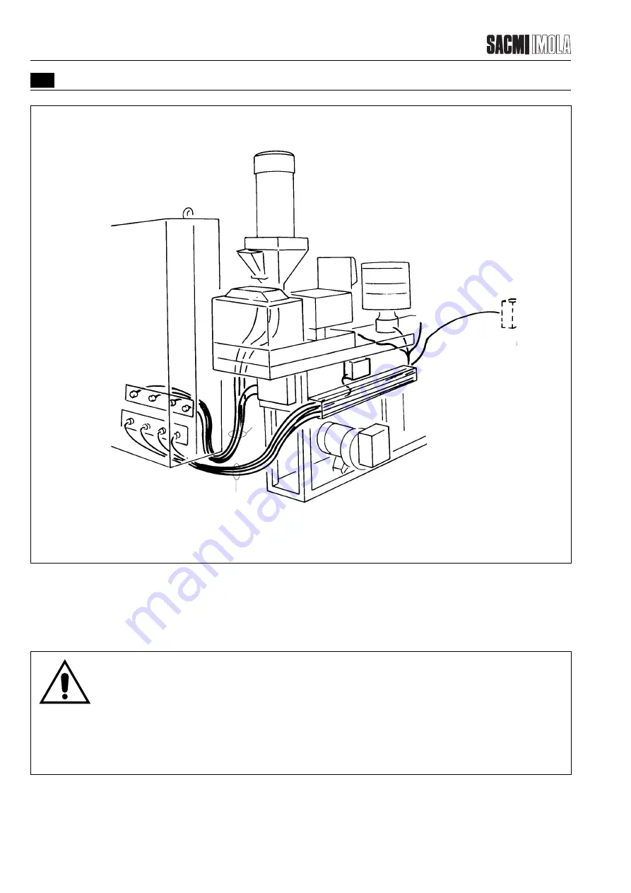
FIGURE 4.3.5.1/B - CONNECTING THE CABLES
B - C
A
T0615
Unwind the cables and lay them on the floor together with those removed from the crates.
Cables A are to be connected directly to the electrical cabinet.
Cables B and C are to be laid in the wireways.
E0004P
WARNING!
First connect the power cables (see relevant table). These cables are stiffer and more difficult to handle and more
space is therefore required.
If possible, the power cables must be grouped together and separated from those leading to the programmable
logic array.
Connect the cables to the machine and inside the electrical cabinet according to markings stamped on each one.
Summary of Contents for PMV 224
Page 2: ...TABLE OF CONTENTS 176 12 A03 0 2 Revision 01 Date 14 11 2001 ...
Page 4: ...TABLE OF CONTENTS 176 12 A03 0 4 Revision 01 Date 14 11 2001 ...
Page 34: ...2 22 176 12 A03 Revision 01 Date 14 11 2001 2 MAIN FEATURES ...
Page 42: ...3 8 176 12 A03 Revision 01 Date 14 11 2001 SAFETY EQUIPMENT AND PRECAUTIONS 3 ...
Page 64: ...5 4 5 START UP 176 12 A03 Revision 01 Date 14 11 2001 ...
Page 70: ...6 6 176 12 A03 Revision 01 Date 14 11 2001 6 OPERATING INSTRUCTIONS ...
Page 126: ...8 30 176 12 A03 Revision 01 Date 14 11 2001 8 MAINTENANCE ...
Page 128: ...9 2 176 12 A03 Revision 01 Date 14 11 2001 9 DECOMMISSIONING ...


