176.12
.A03
7 - 4
ADJUSTMENTS
7
Revision 01 Date 14.11.2001
7.1.3
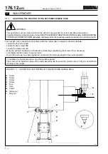
CUTTER CLEARANCE ADJUSTMENT
(References given in figure 7.1.2)
E0004P
WARNING!
This operation must be carried out when the extruder has reached its correct operating temperature.
Carefully follow the instructions given in the SAFETY EQUIPMENT AND PRECAUTIONS chapter, RISKS
DERIVING FROM HIGH TEMPERATURES paragraph and always take the necessary safety precautions to avoid
being burnt.
NOTE: The cutting clearance (Q) should range from 0.02 to 0.05 mm. The cutter (G), when close to the nozzle (N),
rests on the runner (P) which acts as a reference for the height of the cutter.
To adjust or change the cutter clearance (Q), proceed as directed below:
- Place the comparator (R) on the roller holder (M).
- Loosen the screw (O) and lower the runner (P) until the cutter (G) touches the nozzle (N).
- Move the runner (P) up and observe the instrument to make sure that the upward movement of the cutter equals the
desired cutting clearance.
- Fully tighten the clamp screw (O).
Summary of Contents for PMV 224
Page 2: ...TABLE OF CONTENTS 176 12 A03 0 2 Revision 01 Date 14 11 2001 ...
Page 4: ...TABLE OF CONTENTS 176 12 A03 0 4 Revision 01 Date 14 11 2001 ...
Page 34: ...2 22 176 12 A03 Revision 01 Date 14 11 2001 2 MAIN FEATURES ...
Page 42: ...3 8 176 12 A03 Revision 01 Date 14 11 2001 SAFETY EQUIPMENT AND PRECAUTIONS 3 ...
Page 64: ...5 4 5 START UP 176 12 A03 Revision 01 Date 14 11 2001 ...
Page 70: ...6 6 176 12 A03 Revision 01 Date 14 11 2001 6 OPERATING INSTRUCTIONS ...
Page 126: ...8 30 176 12 A03 Revision 01 Date 14 11 2001 8 MAINTENANCE ...
Page 128: ...9 2 176 12 A03 Revision 01 Date 14 11 2001 9 DECOMMISSIONING ...


