176.12
.A03
7 - 14
ADJUSTMENTS
7
Revision 01 Date 14.11.2001
7.4
ADJUSTING THE FORMING UNIT
7.4.1
FORMING PLUNGER CLEARANCE
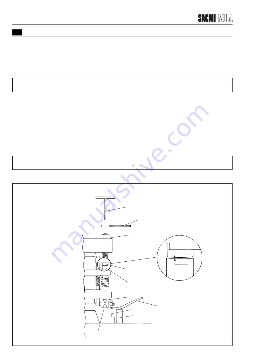
The clearance of the forming plunger is the space left between the lower and forming plungers (1 & 2 respectively),
with no caps, after the lower plunger (1) has reached the cam (3) in its highest position (setting “A” in the diagram).
This distance affects how the liners are formed, especially in the middle. The theoretical setting is A= 1.4 mm. The
optimal setting is determined during machine commissioning.
As even the slightest variations of this value may affect liner formation, this adjustment may need to be made
frequently. To do this, proceed as follows:
- Loosen the ring-nut (5) which holds the forming plunger (2) in place by using the wrench (9) provided.
- Use the wrench (10) to loosen the plunger (2) by a few turns.
- Raise the lower spindle (1) (as shown in the figure) by using a lever (8) and a block (7) (both supplied with the machine).
- Place a shim (6) between the roller (4) and the cam (3) (the size of the shim should be equal to “A”, see diagram).
- With the aid of the wrench (10), screw the forming plunger (2) until the end of the spindle (2) comes into contact with
the end of the lower plunger (1).
- Tighten the ring-nut (5) with the wrench (9). Keep the forming plunger (2) in position with the aid of the wrench (10)
so that it can be locked into position.
- Remove the shim (6).
The correct distance (equal to the size of the spacer on the top of the cam) between the lower and forming plungers
has thus been obtained.
T0620
1
Lower plunger
2
Forming plunger
3
Cam
4
Roller
5
Ring-nut
6
Shim
7
Block
8
Lever
9
Wrench
10 Wrench
10
9
5
2
1
A
2
1
4
8
3
7
6
FIGURE 7.4.1 - ADJUSTING THE PLAY BETWEEN THE FORMING PLUNGER AND THE LOWER PLATE IN THE
FORMING DRUM
Summary of Contents for PMV 224
Page 2: ...TABLE OF CONTENTS 176 12 A03 0 2 Revision 01 Date 14 11 2001 ...
Page 4: ...TABLE OF CONTENTS 176 12 A03 0 4 Revision 01 Date 14 11 2001 ...
Page 34: ...2 22 176 12 A03 Revision 01 Date 14 11 2001 2 MAIN FEATURES ...
Page 42: ...3 8 176 12 A03 Revision 01 Date 14 11 2001 SAFETY EQUIPMENT AND PRECAUTIONS 3 ...
Page 64: ...5 4 5 START UP 176 12 A03 Revision 01 Date 14 11 2001 ...
Page 70: ...6 6 176 12 A03 Revision 01 Date 14 11 2001 6 OPERATING INSTRUCTIONS ...
Page 126: ...8 30 176 12 A03 Revision 01 Date 14 11 2001 8 MAINTENANCE ...
Page 128: ...9 2 176 12 A03 Revision 01 Date 14 11 2001 9 DECOMMISSIONING ...


