176.12
.A03
7 - 5
ADJUSTMENTS
7
Revision 01 Date 14.11.2001
A
D
1
E
2
F
F
A
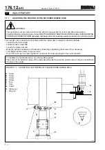
FIGURE 7.1.4 - POSITIONING THE EXTRUDER NOZZLE
B
C
A
Precision comparator (accuracy in 1/100 of mm)
B
Magnetic support block
C
Insertion drum
D
Screws
E
Difference in level
F
Nozzle
T0417
7.1.4
POSITIONING THE EXTRUDER NOZZLE
Proceed as directed below when removing and re-fitting the extruder nozzle.
- Place the magnetic support block (B) of the comparator (A) on the side of the insertion drum (C).
- Bring the comparator (A) to one end (1) of the nozzle (F).
- By using the handwheel, turn the drum (C) until the comparator (A) reaches the opposite end (2) of the nozzle (F).
- There should be a difference in level along the plane where the measurements are taken, i.e. “E” must be between
0.0 and 0.03 mm.
The lowest part should be at the point where the cutter moves down close to the nozzle.
If the measurement is incorrect:
- Loosen the screws (D), which secure the nozzle to the extrusion head, and turn the nozzle until the correct
measurement is obtained.
- Fully tighten the screws (D).
Summary of Contents for PMV 224
Page 2: ...TABLE OF CONTENTS 176 12 A03 0 2 Revision 01 Date 14 11 2001 ...
Page 4: ...TABLE OF CONTENTS 176 12 A03 0 4 Revision 01 Date 14 11 2001 ...
Page 34: ...2 22 176 12 A03 Revision 01 Date 14 11 2001 2 MAIN FEATURES ...
Page 42: ...3 8 176 12 A03 Revision 01 Date 14 11 2001 SAFETY EQUIPMENT AND PRECAUTIONS 3 ...
Page 64: ...5 4 5 START UP 176 12 A03 Revision 01 Date 14 11 2001 ...
Page 70: ...6 6 176 12 A03 Revision 01 Date 14 11 2001 6 OPERATING INSTRUCTIONS ...
Page 126: ...8 30 176 12 A03 Revision 01 Date 14 11 2001 8 MAINTENANCE ...
Page 128: ...9 2 176 12 A03 Revision 01 Date 14 11 2001 9 DECOMMISSIONING ...


