176.12
.A03
7 - 19
ADJUSTMENTS
7
Revision 01 Date 14.11.2001
7.5.2
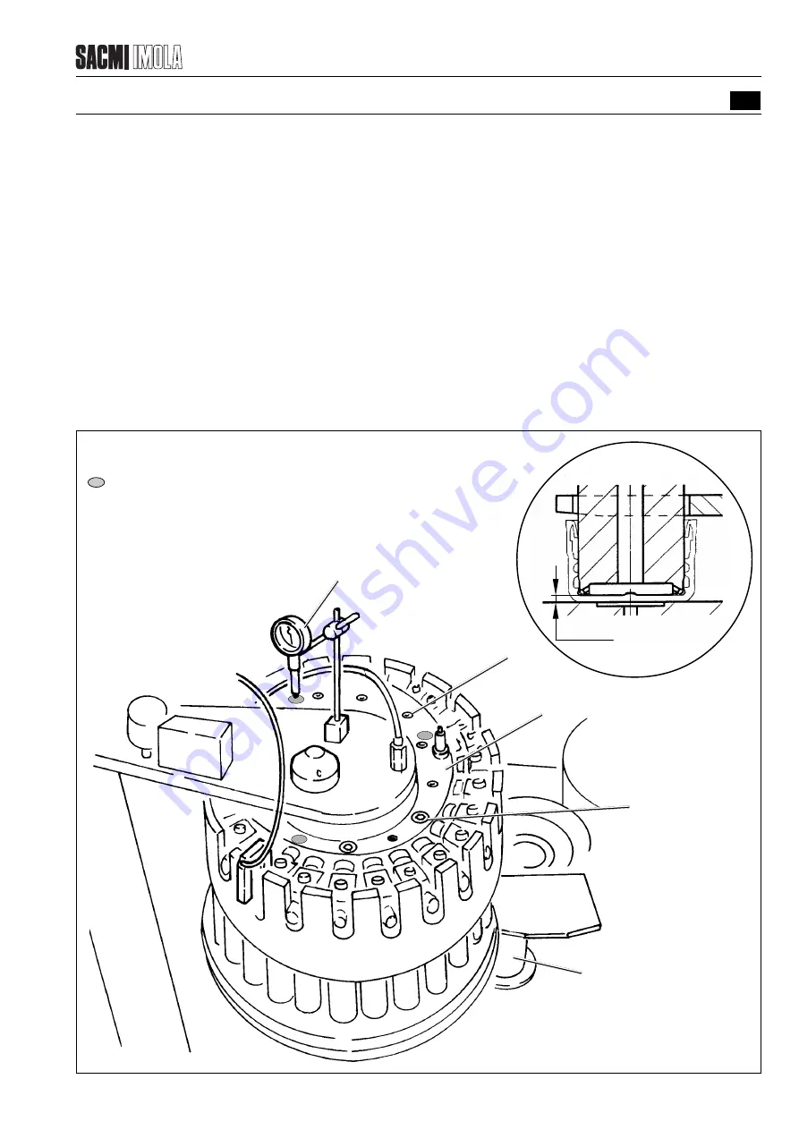
ADJUSTING THE HEIGHT OF THE SENSING SPINDLES
To make this adjustment it is necessary to raise or lower the cam which the sensing spindles are attached to. The
central sensors must be positioned at a distance Y from the surface the caps rest on as indicated in the diagram.
- Position three comparators (1) on the cam (4) at 120
°
as illustrated in the diagram.
- Reset the comparators.
- Loosen the screws (2).
- Tighten or loosen the grub screws (3) in order to raise or lower the cam (4). All the comparators should indicate the
same degree of movement.
- Tighten the screws (2).
FIGURE 7.5.2 - ADJUSTING THE HEIGHT OF THE SENSING SPINDLES
•
1
T2509
T0437
3
2
4
5
Position where the
comparators should rest
1
Comparator
2
Screw
3
Grub screw
4
Cam
5
Sensing spindle
Y
Summary of Contents for PMV 224
Page 2: ...TABLE OF CONTENTS 176 12 A03 0 2 Revision 01 Date 14 11 2001 ...
Page 4: ...TABLE OF CONTENTS 176 12 A03 0 4 Revision 01 Date 14 11 2001 ...
Page 34: ...2 22 176 12 A03 Revision 01 Date 14 11 2001 2 MAIN FEATURES ...
Page 42: ...3 8 176 12 A03 Revision 01 Date 14 11 2001 SAFETY EQUIPMENT AND PRECAUTIONS 3 ...
Page 64: ...5 4 5 START UP 176 12 A03 Revision 01 Date 14 11 2001 ...
Page 70: ...6 6 176 12 A03 Revision 01 Date 14 11 2001 6 OPERATING INSTRUCTIONS ...
Page 126: ...8 30 176 12 A03 Revision 01 Date 14 11 2001 8 MAINTENANCE ...
Page 128: ...9 2 176 12 A03 Revision 01 Date 14 11 2001 9 DECOMMISSIONING ...


