background image

3

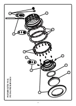
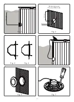
Secure the clamp (nº 5) to the pool wall using 16 screws, DIN 7982 5,5 x 25 (no. 12) (Fig. 4).

4. ASSEMBLY: 

After installation of the housing and the clamp, assemble the floodlamp.

To connect the floodlamp to the electric power supply insert the cable through the gland seal nut (nº 8). 

Tighten the gland seal nut until you can verify that the cable will not yield when you pull on it with your hand. 

Take the precaution of leaving 1.5 m of cable wound on the base of the floodlamp in order to be able to 

remove the floodlamp to the edge of the pool in the event that lamp replacement or handling is required. (Fig. 

5). Insert the entire floodlamp assembly in the housing (Fig 6).

5. MAINTENANCE:

To remove the floodlamp to the edge of the swimming pool (Fig. 5) loosen until the fastening dog yields 

sufficiently so that the floodlamp unit can be separated from the housing. 

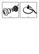
To remove the lamp, unscrew the 6 screws (nº 1) which secure the decorative ring to the base of the 

floodlamp (nº 3) (Fig. 7). 

Remove the lamp (nº 10) from the inside of the base of the floodlamp and disconnect the two terminals, 

loosening the two screws which secure them to the lamp. (Fig. 8). 

Change the lamp and assemble the Floodlamp, in the opposite order described in point 4 of assembly, taking 

special care to:


• Connect the cable terminals to the lamp, using the 2 screws supplied with the lamp (Fig. 9).


• Fully centre the 110x11 O-ring (nº 2) in its seat.


• Firmly tighten the nuts.

Attention:

• Before any handling ensure that there is NO voltage supplied to the floodlamp.

• Connect the cable terminals to the lamp, using the 2 screws supplied with the lamp (Fig. 9).

• In order to ensure full watertightness, clean the seat of the O-ring (nº 2) for the lamp or replace the O-ring 

if you observe any notches or permanent damage.

6. START-UP: 

Ensure that the voltage the lamp receives is never greater than 12 V.

The floodlamp should only operate underwater while secured to the vertical walls of the pool. Never switch 

on the floodlamp if it is not underwater.

7. SAFETY WARNINGS:

• The persons who are in charge of assembly should have the required qualificatlons for this type of work.

• Avoid making contact with the electric voltage.

• Comply with the current standards regarding accident prevention.

• In this regard, the IEC 364-7-702 standards must be observed. WIRING IN BUILDINGS. SPECIAL 

WIRING. SWIMMING POOLS.

• Any operation related to the maintenance or replacement of parts should be performed with the floodlamp 

disconnected from the electric power system.

• Do not handle with wet feet.

• The manufacturer is not responsible in any circumstances for assembly, installation or start-up of any 

electric components which have been inserted or handled at locations other than its own premises.

Summary of Contents for PAR56

Page 1: ...RO SUBACQUEO LED PAR56 UNTERWASSER SCHEINWERFER LED PAR56 FARO SUBACQUEO LED PAR56 INSTALLATION AND MAINTENANCE MANUAL MANUEL D INSTALLATION ET D ENTRETIEN MANUAL DE INSTALACI N Y MANTENIMIENTO MANUAL...

Page 2: ...install in vertical positlon with the lamp facing downwards To correctly light a swimming pool we recommend you Install a lamp in the range PAR56 V1 every 20 m of water surface Note Recommendation val...

Page 3: ...to Connect the cable terminals to the lamp using the 2 screws supplied with the lamp Fig 9 Fully centre the 110x11 O ring n 2 in its seat Firmly tighten the nuts Attention Before any handling ensure...

Page 4: ...ulation ou rajout de composants lectriques qui ne se seraient pas produits chez lui 3 INSTALLATION Ne jam is installer le projecteur en positlon verticale avec la lampe orient e vers le bas Afin d cla...

Page 5: ...ter les cosses du c ble la lampe en utilisant les 2 vis fourmes avec la lampe Fig 9 Placer le joint torique 110x11 n 2 bien centr dans son logement Bien serrer tous les crous Attention Avant toute man...

Page 6: ...esponsabiliza del montaje instalaci n o puesta en funcionamiento de cualquier manipulaci n o incorporaci n de componentes el ctricos que no se hayan llevado a cabo en sus instalaciones 3 INSTALACI N N...

Page 7: ...punto 4 de montaje teniendo especial cuidado en Conectar los terminales del cable a la l mpara utilizando los 2 tornillos suministrados con la l mpara Fig 9 Poner la Junta t rica 110x11 n 2 bien cent...

Page 8: ...componenti elettrici che sono stati manipolati o introdotti al di fuori dei suoi stabilimenti 3 INSTALLAZIONE Non installare mal in posizione verticale con la lampada verso il basso Per illuminare co...

Page 9: ...cura di Collegare i terminali del cavo alia lampada usando le due viti fornite con la lampada Fig 9 Metiere a guarnizione tonca 110x11 n 2 ben centrata nel suo allogglamento Stnngere bene tutti i dadi...

Page 10: ...ei Verantwortung f r die Montage Installation oder Inbetriebnahme sofern irgendeine Art Handhabung oder Einbau von Elektrokomponenten nicht in seinem Betrieb durchgef hrt worden sind 3 INSTALLATION De...

Page 11: ...ie oben im Punkt 4 beschrieben wobei auf folgendes besonders geacntet werden mu Die Kabelschuhe werden an der Lampe angeschlossen wof r die beiden mit der Lampe mitgelieferten Schrauben zu verwenden s...

Page 12: ...onamento por qualquer manipula o ou incorpora o de componentes el tricos que n o tenham sido realizadas nas suas instala es 3 INSTALA O N o instalar nunca na posi o vertical com a l mpada para baixo P...

Page 13: ...o l mpada utilizando os 2 parafusos fornecidos com a l mpada Fig 9 Para assegurar uma perfeita estanqueidade dever limpar o assento da junta t rica n 2 da l mpada ou substituir a junta se observar alg...

Page 14: ...14 1 10 2 4 3 7 5 9 11 8 6 PREFABRICATED POOL PISCINA PREFABRICADA...

Page 15: ...eur 3 4403010305 Niche d ampoule de projecteur 4 4403014304 Clip fixation projecteur 5 4403013506 Bride fixation projecteur Parker 6 4403013501 Joint adhesif projecteur 7 4403010312 Presse etoupe proj...

Page 16: ...4 4403014304 Befestigungsclipsatz uws 5 4403013506 Flansch mit schrauben uws Parker 6 4403013501 Dichtungen f r flansch uws 7 4403010312 Quetschverschraubung geh use uws M 25 8 4403010313 Wanddurchf h...

Page 17: ...17 Fig 1 Fig 3 Fig 6 Fig 2 Fig 5 Fig 4 Fig 7 Prefabricated pool Piscina prefabricada 700 mm 700 mm 240mm...

Page 18: ...18 Fig 8 Fig 9...

Page 19: ...atibilit lectromagn tique 2004 108 CEE La Directive des appareils basse tension 2006 95 CEE La R glementation Europ enne EN 60598 1 EN 60598 2 18 dans toutes ses modifications DICHIARAZIONE CE DI CONF...

Page 20: ...serviamo il diritto di cambiare totalmente o parzialmente le caratteristiche tecniche dei nostri prodotti ed il contenuto di questo documento senza nessum preavviso Wir behalten uns das recht vor die...

Reviews: