26
Keep the manual for future reference - For more informations visit www.saerelettropompe.com
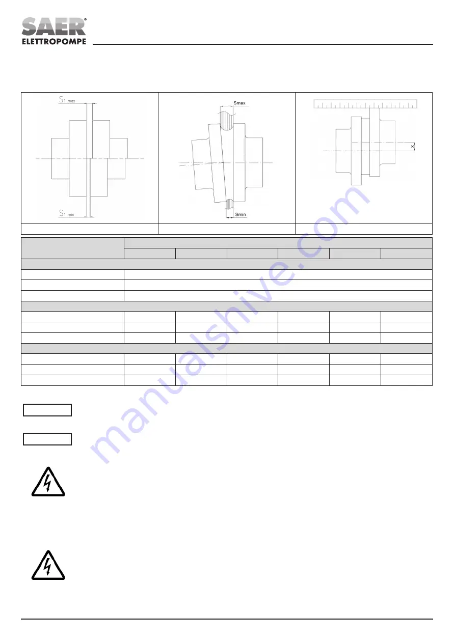
- Check the radial displacement of the two semi-couplings by using a bracket or a comparator (x).
- If necessary, correct the angle alignment by moving the motor (through the use of the shims or, through the adjustment screws placed in the feet of
the motor, if equipped).
- When the alignment is completed, replace the coupling guard.
Axial misalignment
Angular misalignment
Radial misalignment
Ø Coupling diameter [mm]
1/min
750
1000
1500
1800
3000
3600
Axial misalignment [mm]
≤ 145
S
1max
=4 ; S
1min
=2
145 ÷ 250
S
1max
=6 ; S
1min
=2
≥ 250
S
1max
=8 ; S
1min
=3
Angular misalignment (S
max
- S
min
) [mm]
≤ 145
0,25
0,2
0,2
0,15
0,15
0,1
145 ÷ 250
0,35
0,3
0,25
0,2
0,2
0,15
≥ 250
0,45
0,4
0,3
0,25
0,25
0,2
Radial misalignment x [mm]
≤ 145
0,25
0,2
0,2
0,15
0,15
0,1
145 ÷ 250
0,35
0,3
0,25
0,2
0,2
0,15
≥ 250
0,45
0,4
0,3
0,25
0,25
0,2
*This table is valid only for couplings supplied by SAER.
WARNING!
Do not use the pump without the properly coupling guard, installed in the appropriate way.
The coupling guard and coupling must not touch each other.
AUXILIARY CONNECTIONS
WARNING!
Verify the presence and proper installation of the necessary auxiliary connections.
ELECTRICAL CONNECTIONS
The connection to the power grid must be done in the respect of the local and national standards of the electric system of the place
where the pump is installed.
Furthermore, respect the connection diagrams supplied with the motor and with the control panel.
Perform the earth connection before all the other connections.
Verify the correct operation of the electric equipment (control panel etc…).
CHECKS ON THE ELECTRICAL SYSTEM
Verify that the electrical system corresponds to the CEI EN 60204-1 standard and to the local and national standards of the electric
system of the place where the pump is installed.
Verify:
- the existence of an earth connection,
- the presence of an omni-polar switch disconnector that can disconnect all the feeding cables to insulate the motor in case of
malfunction or small maintenance operations (the disconnection device from the supply mains must be over-voltage III category)
- the presence of an emergency stop button.
- The presence of a residual current device (RCD) with rated residual operating current not exceeding 0,03 A.
- for three-phase pumps and for pumps without integrated protection device: the presence of a thermal protection device adjusted on
a maximum absorbed current not higher than 5% the current stated in the label and with an operating time lower than 30 seconds.
The feeding cable must have adequate section in order to avoid a voltage drop greater than 3 % of the nominal voltage and to operate
within the rated temperature.
For further limitations, please refer to the motor instruction manual.


