background image

20

ELECTROMAGNETIC COMPATIBILITY INFORMATION 

In IEC/EN 60601-1-2 4th edition. These limits are designed to provide reasonable protection against harmful

interference in a typical medical installation. This equipment generate, use and can radiate radio frequency

energy and, if not installed and used in accordance with the instructions, may cause harmful interference

to other devices in the vicinity. However, there is no guarantee that interference will not occur in a particular

installation. If this equipment does cause harmful interference to other devices, which can be determined

by turning the equipment off and on, the user is encouraged to try to correct the interference by one

or more of the following measures:

 - Reorient or relocate the receiving device.

 - Increase the separation between the equipment.

 - Connect the equipment into an outlet on a circuit different from that to which the other device(s) are connected.

 - Consult the manufacturer or filed service technician for help.

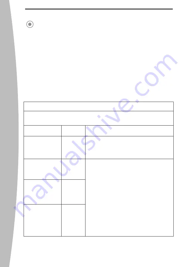
Electromagnetic Emissions

The TRAUS SIP20 is intended for use in the electromagnetic environment specified below. The customer

or the user of the TRAUS SIP20 should assure that is used in such an environment.

Emission test

Compliance

Electromagnetic environment - guide

RF emission – CISPR 11

EN 55011

Group 1

TRAUS SIP20 uses RF energy for internal operation.

Therefore, its radiofrequency emissions are very low and

are not likely to cause any interference in nearby equipment.

RF emission – CISPR 11

EN 55011

Class A

Harmonic emission – 

IEC 61000-3-2

EN 61000-3-2

Class A

Voltage fluctuations

Flicker emission – 

IEC 61000-3-3

EN 61000-3-3

Compliance

TRAUS SIP20 covers devices for usage in all establishments

other than domestic and that are not directly connected to

a low voltage power supply network, which supplies

domestic environment.

This is a class A product. In a domestic environment this

product may cause radio interference in which case the

user may be required to take adequate measures.

Summary of Contents for TRAUS SIP20

Page 1: ...USER MANUAL www saeshin com SIP20...

Page 2: ...NTS PART NAME OF CONTROL BOX BUTTONS ON THE OPERATION PANEL LCD WINDOW BUTTONS ON THE FOOT CONTROLLER CONNECTION OF EACH PART OPERATION PROCESS MAINTENANCE OF THE PRODUCT ATTENTION PRODUCT SPECIFICATI...

Page 3: ...otection against electric shock Class equipment Degree of protection against electric shock Type B applied part Classification according to the degree of protection against ingress of water as detaile...

Page 4: ...ste after use Contact manufacturer if an incorrect display appears on the screen Do not drop or bang the product Do not damage the irrigation tube as it will not work properly due when the tube is bro...

Page 5: ...cause electric shock and or fire Unauthorized modification and dismantling is prohibited Do not use a solvent such as thinner or benzene for cleaning Please use an absorbent or alcohol to wipe the co...

Page 6: ...oller The ergonomically designed Foot Controller with main functions can be used during any surgery for user s convenience Setting with SETUP Mode Auto Calibration Sound Volume Control and Program Res...

Page 7: ...olution is not included in a set Irrigation tube and Y Tube are disposable Do not use them again Component Component Control Box Internal Spray Nozzle Optional Angle Handpiece BLDC Motor Optional Moto...

Page 8: ...NTROL BOX Foot Controller Connector Fuse Box Main Power Switch Menu Button OK Button Control Button Gear Ratio Button Optic Button Irrigation Button Rotation Direction Button LCD Display Hanger Hole M...

Page 9: ...Optic motor Control Button This is used for selecting the program number SETUP menu and adjusting the rpm torque The setting range of rpm and torque are different from gear ratio OK Button This is us...

Page 10: ...the corresponding menu is selected the RPM can be adjusted using the and buttons 7 Torque Menu Display When the corresponding menu is selected the torque can be adjusted using the and buttons 8 SETUP...

Page 11: ...n after releasing the button 2 Operation Direction Button Use the button for selecting the operation direction Press the button change the rotary direction 3 Irrigation Pump Button Use the button for...

Page 12: ...sure the power is off Otherwise it might cause a malfunction CONNECTION OF EACH PART 2 Foot Controller Connection Insert the foot controller connector Check if the holes and pins of foot controller co...

Page 13: ...r You must close the cover and use it as your fingers may get stuck Make sure the pump roller cover is correctly close Insert the irrigation tube correctly Locate the Irrigation tube correctly when in...

Page 14: ...ry type If the pump is in operation mode but water does not come out of the handpiece the tube may be broken or damaged If the user did not remove the internal spray nozzle and pressed the button or o...

Page 15: ...e bur Insert the bur to the angle handpiece Insert certainly the bur while pushing the head button on angle handpiece Release the button Pull out the bur to check it 2 Disconnecting the bur Pull out t...

Page 16: ...go to program number menu 2 Press the Control Button to select the desired program number 3 After setting the desired value by referring to the operation method keep pressing OK Button for 3 seconds...

Page 17: ...Other Function SETUP Press the Menu Button to go to SETUP Menu and press the OK Button Press the Control Button to the desired item Press the OK Button in SETUP to save and return to main After conne...

Page 18: ...ies do not activated Cause The motor connection is not proper or the motor is defective Remedy Make sure that motor properly connected Contact the manufacturer if the remedies do not activated Cause T...

Page 19: ...is determined not to be visually clean at the end of the cleaning step the user should either repeat the relevant previous cleaning steps or safely dispose of the device so that a visibly soiled devi...

Page 20: ...e product Do not put any physical pressure on the all cords 4 When the products are not using for a long term please be advised to the followings Turn off the power and unplug the cord Check the cord...

Page 21: ...Handpiece 4 Foot Controller Model Name IPX8 TRAUS FUS10 Classification according to the degree of protection against ingress of water IEC 60529 Model Name Gear ratio Optic Non optic Bur Replacement T...

Page 22: ...the other device s are connected Consult the manufacturer or filed service technician for help Electromagnetic Emissions The TRAUS SIP20 is intended for use in the electromagnetic environment specifie...

Page 23: ...t 8 angles 0 UT for 1 cycle 70 UT for 25 30 cycles 0 UT for 250 300 cycle 8kV contact 15kV air 2kV for power supply lines 1kV for input output lines 1kV differential mode 2kV common mode 0 UT for 0 5...

Page 24: ...o AM FM radio broadcasts and TV broadcasts cannot be determined exactly by theory To assess the electromagnetic environment due to fixed radiofrequency emitters an electromagnetic environment measurem...

Page 25: ...lection from structures objects and persons 150 kHz 80 MHz d 1 2 P Separation distance according to frequency of transmitter m 800 MHz 2 7 GHz d 2 3 P 0 01 0 12 0 12 0 23 0 1 0 38 0 38 0 73 1 1 2 1 2...

Page 26: ...use or improper use and treatment Use the product with incorrect input voltage AC voltage Drop the device during setting moving using Use the not recommended consumables or accessories Malfunction aft...

Page 27: ...ctric shock Type B Manufacturer Consult Instruction For Use General Caution Sign General Warning Sign Alternating Current Power On Main power switch Power Off Main power switch This product should not...

Page 28: ...53 580 0999 1 52 5 Tel 053 587 2345 Fax 053 580 0918 SOM S048S E Rev 3 2022 07 27 www saeshin com traus saeshin com MERIDIUS MEDICAL EUROPE LIMITED Unit 3D North Point House North point Business Park...

Reviews: