background image

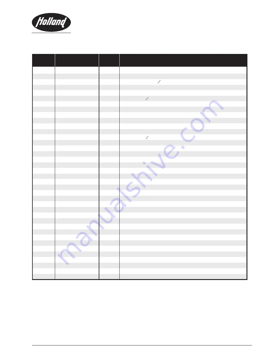
ITEM

PART NO.

NO. 

REQ'D

PART NAME

1

XA-77144

1

Top plate

2

XB-76030

2

Hex. bolt, M20 x 55

3

XB-76031

2

Nut M20

4

XB-76023-1

8

Countersunk bolt M16 x 50

5

XB-76025

8

Washer O16

6

XB-76026-1

8

Locknut M16

7
8

XA-76152

2

Guide plate

9

XA-76163

1

Release bolt

10

XA-76168

1

Guide Ring

11

XA-76157

1

Pressure Plate

12

XB-76033

4

Shock Absorber Element

13

33023

13

Washer O10

14

XA-76162

1

Bushing

15

XB-76034

1

Hex. bolt M10 x 35

16

XA-76156

1

Lock bolt

17

XA-76159

1

Operating Handle

18

XA-76160

1

Operating Handle

19

XA-76155

1

Control lever

20

XA-76166

4

Bushing

21

XA-76166-1

1

Bushing

22

XA-76167

1

Bushing

23

XA-76158

1

Link lever

24

XB-76028

1

Countersunk bolt M10 x 40

25

XB-76024-1

2

Countersunk bolt M16 x 30

Bushing

26

XB-76038

2

Countersunk bolt M10 x 45

27

XA-76154

1

Release lever

28

31008

3

Hex. bolt M10 x 25
Hex. bolt M10 x 50

29

31032

2

30

32008

8

Locknut M10

XB-76032 

2

Washer, Plain O20

31

31038

3

Countersunk bolt M10 x 35

32
33
34
35

36

37
38

XA-76169
XA-76176
XB-76104

XA-76134
XB-76008
XB-D-05843-1

XA-76124

1
1
1

1
1

2
1

Bushing
Brake actuator

PA R T S   L I S T   F O R   TO P  P L AT E  A S S E M B LY  X A - 7 6 1 0 1  

10

Spring guide
Compression spring

Extension spring

Release lever

SAF-HOLLAND Group

Summary of Contents for FW6170

Page 1: ...tch before coupling A Inspect the railcar hitch for visible damage prior to each loading operation B The railcar hitch must be properly lubricated 2 Coupling operation A B The trailer should be lowered until the trailer plate is in contact with the railcar hitch top plate and the kingpin is correctly located in the guide ring NOTE The locking mechanism automatically opens when the kingpin is enter...

Page 2: ...hind or to the side Kingpin is on the top TRAILER PLATE RAILCAR HITCH TOP PLATE NO GAP GAP VISIBLE ONLY HANDLE IS SHOWING VISUAL INDICATOR RETAINING NOTCH IN THE HANDLE IS SHOWING RETAINING NOTCH IN THE HANDLE IS HOOKED ONTO THE RAILCAR HITCH TOP PLATE RAILCAR HITCH IS OPEN RAILCAR HITCH IS LOCKED 3 Inspection of the railcar hitch after loading A B The operating handle is in the fully retracted po...

Page 3: ... back inwards the next height has been reached 3 In order to be correctly locked the control lever must be located completely under the square block This will be visible to the correlation of the markings on the locking lever and the base plate 3 If the square is not parrellel to the base plane so the crank must be turned further until the locking lever can pass under the square block Ignoring thi...

Page 4: ...sure that all moving parts are clean and adequately lubricated Attention should be paid especially to the following lubrication points 1 All parts of the locking mechanism 2 Bevel gear every 8 months or if required 3 4 5 Spindle Outer surface of the lifting arms Contact surface of sliding frame guide shaft 5 5 Notes When cleaning the railcar hitch environmentaly harmful substances may be used We p...

Page 5: ...on and maintenance procedures for the railcar hitch are to be performed every four months but this frequency is depending upon its usage At each service the railcar hitch has to be checked for damage and to be repaired when indicated The function of the railcar hitch has to be checked after every service 1 Check the complete railcar hitch thoroughly Replace any missing or damaged bolts and nuts 2 ...

Page 6: ...ch especially the locking mechanism and the king pin must be checked for damage Damaged parts must be replaced Immediately Important Failure to follow these instructions could result in an accident The shock absorbers and the lock plunger can be replaced with the railcar hitch in situ In this case the railcar hitch must be in the upper position Quantity Shock Lock Absorber Plunger Torque Wrench He...

Page 7: ...nd fix it with bolt 11 Torque Md 115 Nm 9 Secure bolt with nut 10 1 Loosen the lock nut 10 and the bolt 11 2 Remove pressure plate 9 3 Slide guide ring 8 4 Remove old shock absorber elements 1 5 Insert new shock absorber elements 6 Insert pressure plate and tighten the bolt Torque Md 115 Nm 7 Secure bolt with lock nut 10 7 SAF HOLLAND Group Item Description Part No Quantity Shock absorber XB 76033...

Page 8: ...handle with new split pin 8 SAF HOLLAND Group Item Description Part No Quantity Operating Handle XA 76131 Split Pin XA 76044 1 1 1 1 2 Replacement of the operating handle 1 2 Mount handle from inside The operating handle can be replaced with the railcar hitch in situ The railcar hitch must be in the upper position ...

Page 9: ...RAILCAR HITCH TOP PLATE ASSEMBLY XA 76101 9 NOTE For simplification the top plate assembly is shown upside down SAF HOLLAND Group ...

Page 10: ...perating Handle 19 XA 76155 1 Control lever 20 XA 76166 4 Bushing 21 XA 76166 1 1 Bushing 22 XA 76167 1 Bushing 23 XA 76158 1 Link lever 24 XB 76028 1 Countersunk bolt M10 x 40 25 XB 76024 1 2 Countersunk bolt M16 x 30 Bushing 26 XB 76038 2 Countersunk bolt M10 x 45 27 XA 76154 1 Release lever 28 31008 3 Hex bolt M10 x 25 Hex bolt M10 x 50 29 31032 2 30 32008 8 Locknut M10 XB 76032 2 Washer Plain ...

Page 11: ... 7 8 7 6 35 36 6 7 28 9 5 36 11 7 35 33 6 7 25 16 38 27 37 14 38 27 37 15 42 24 17 18 4 20 17 42 1 32 44 3 23 13 26 21 43 22 10 22 21 10 43 26 13 23 3 32 44 12 45 46 47 29 3 12 2 31 32 3 29 11 SAF HOLLAND Group RAILCAR HITCH BASE ASSEMBLY XA 76100 49 ...

Page 12: ... 34011 2 Spring Pin O10 x 70 22 2 Spring Pin O10 x 35 23 XA 76131 2 Operating Handle 24 XA 76126 1 Sliding Frame 25 XA 76177 2 Spindle Nut 26 XA 76170 4 Spacer bush 27 XA 76040 1 Tension Spring 28 XA 76179 2 Extension Shaft 29 30 XA 76173 A 2 Cover Plate Cover Plate Cover Plate Crank Handle 31 XB 76060 14 Screw M6 x 12 2 Hex bolt M10 x 25 1 Hex bolt M10 x 30 33 32008 3 Nut Lock M10 34 2 Spring pin...

Page 13: ... 35 33 6 7 25 16 37 14 37 15 42 48 24 17 18 4 20 17 42 1 32 44 3 23 13 26 21 43 22 10 22 21 10 43 26 13 23 3 32 44 12 29 3 12 2 31 32 3 29 13 SAF HOLLAND Group RAILCAR HITCH BASE ASSEMBLY XA 76100 OLD VERSION 49 48 38 38 38 27 27 40 41 38 27 38 27 40 41 41 40 41 40 45 46 ...

Page 14: ...O10 x 70 22 2 Spring Pin O10 x 35 23 XA 76131 2 Operating Handle 24 XA 76126 1 Sliding Frame 25 XA 76177 2 Spindle Nut 26 XA 76144 4 Clamp Ring 27 XA 76040 1 Tension Spring 28 XA 76179 2 Extension Shaft 29 30 XA 76173 A 2 Cover Plate Cover Plate Crank Handle Plastic Cap 31 XB 76060 14 Screw M6 x 12 2 Hex bolt M10 x 25 1 Hex bolt M10 x 30 33 32008 3 Nut Lock M10 34 2 Spring pin O10 x 45 Spring pin ...

Page 15: ...LLAND VKT GmbH Julius Bührer Str 12 78224 Singen Germany Phone 49 0 7731 1443 344 Fax 49 0 7731 1443 200 Copyright August 2010 SAF HOLLAND All information contained in this document is correct at time of copyright and is subject to change without notification all rights reserved www safholland com XL FW1141 07 ...

Reviews: