background image

6

XL-FW20017RM-en-US · 2014-06-02 · Amendments and Errors Reserved · © SAF-HOLLAND, Inc., SAF-HOLLAND, HOLLAND, SAF, and 

logos are trademarks of SAF-HOLLAND S.A., SAF-HOLLAND GmbH, and SAF-HOLLAND, Inc.

Replacement Procedures

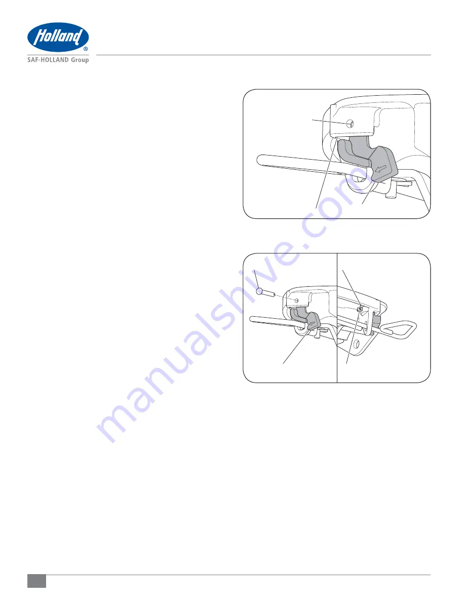
Figure 10

8.  Position the lock indicator into the pocket on the release 

handle window of the casting, ensuring that the lock 
indicator is in the correct orientation 

(Figure 10)

.

9.  Insert the lock indicator pin through the casting hole 

and the lock indicator and attach with 1/8

"

 cotter pin. 

Spread both legs of the cotter pin at a 20° angle minimum 

(Figure 11)

.

ALIGN HOLES

POCKET OF CASTING

LOCK INDICATOR

Figure 11

LOCK INDICATOR

LOCK INDICATOR PIN

LOCK INDICATOR PIN

SPREAD LEGS OF COTTER PIN

Summary of Contents for Holland FWS1

Page 1: ...ardous situation which if not avoided could result in property damage Indicates a potentially hazardous situation which if not avoided could result in minor or moderate injury Indicates a potentially hazardous situation which if not avoided could result in death or serious injury General Servicing and Safety Instructions Read and observe all Warning and Caution hazard alert messages The alerts pro...

Page 2: ...ment verify the correct replacement kit for the fifth wheel top plate being repaired Fifth wheel serial tags are located on the left side of the fifth wheel top plate above the fifth wheel bracket pin or on the pickup ramps as illustrated The part number and serial number are listed on the tag as indicated Figure 1 Figure 1 U S AND FOREIGN PATENTS APPLY Model No XXXXXXXXXXXX Serial No XXXXXXXXXXXX F...

Page 3: ...5 RK 11112 AIR RELEASE TOUCHLOC HANDLE FIGURE 3 ITEM DESCRIPTION PART NUMBER QTY 1 Release Handle XA 11112 1 2 Cotter Pin 1 8 84261 1 3 Safety Indicator XD 11121 1 4 Roll Pin 3 16 9900181 1 5 Safety Indicator Pin XB 10996 1 RK 10990 REPLACEMENT KIT CONTENTS FIGURE 2 ITEM DESCRIPTION PART NUMBER QTY 1 Release Handle XA 10990 1 2 Washer XB T 49 1 3 Cotter Pin 1 8 84261 1 4 Safety Indicator XD 11121 ...

Page 4: ... Number 4000171 Figure 4 2 Working on the underside of the top plate remove the cotter pin from the lock indicator pin and detach the lock indicator from the fifth wheel Discard the cotter pin lock indicator pin and lock indicator Figure 5 3 FWS1 FWS2 Model Remove the cotter pin and washer from the end of the release handle Figure 6 FWS1 FWS2 Air Release Touchloc Model Remove the roll pin from the...

Page 5: ...ver bar Figure 7 5 Discard release handle washer and cotter pin roll pin 6 Insert the new release handle through the release handle window in the casting and into the lever bar Figure 8 7 FWS1 FWS2 Model Install the new washer and 3 16 cotter pin into the end of the new release handle Spread both legs of the cotter pin at a 20 angle minimum Figure 9 FWS1 FWS2 Air Release Touchloc Model Install the...

Page 6: ...r into the pocket on the release handle window of the casting ensuring that the lock indicator is in the correct orientation Figure 10 9 Insert the lock indicator pin through the casting hole and the lock indicator and attach with 1 8 cotter pin Spread both legs of the cotter pin at a 20 angle minimum Figure 11 ALIGN HOLES POCKET OF CASTING LOCK INDICATOR Figure 11 LOCK INDICATOR LOCK INDICATOR PI...

Page 7: ...T use any fifth wheel which does not operate properly Failure to repair an improperly operating fifth wheel could result in tractor trailer separation which if not avoided could result in death or serious injury 1 If fifth wheel is locked lift release handle up pull completely out and up again to hook on casting If air release equipped actuate fifth wheel control valve to open lock Figure 12 2 Fir...

Page 8: ... Figure 16 6 To adjust lock With the lock tester still locked in the fifth wheel lift up on fifth wheel ramps and rotate fifth wheel to its forward most position toward the cab Remove clinch pin from the bottom of the lock adjustment pin Figure 17 Lift the lock adjustment pin and rotate clockwise to the next adjustment position shown on the face of fifth wheel Figure 18 Push the lock adjustment pi...

Page 9: ...ront edge of the kingpin on the lock tester and the front lock radius of the fifth wheel Figure 19 IMPORTANT A minimum of 1 16 1 5 mm free play is critical to proper operation of the fifth wheel If there is NOT 1 16 1 5 mm minimum free play in the lock the fifth wheel lock adjustment pin MUST be rotated counterclockwise to the next lower position Re verify that 1 16 1 5 mm minimum play exists using ...

Page 10: ...10 XL FW20017RM en US 2014 06 02 Amendments and Errors Reserved SAF HOLLAND Inc SAF HOLLAND HOLLAND SAF and logos are trademarks of SAF HOLLAND S A SAF HOLLAND GmbH and SAF HOLLAND Inc Notes ...

Page 11: ...11 XL FW20017RM en US 2014 06 02 Amendments and Errors Reserved SAF HOLLAND Inc SAF HOLLAND HOLLAND SAF and logos are trademarks of SAF HOLLAND S A SAF HOLLAND GmbH and SAF HOLLAND Inc Notes ...

Page 12: ...ginal component assembly SAF HOLLAND Original Parts are tested and designed to provide maximum performance and durability Will fits look alikes or worse yet counterfeit parts will only limit the performance potential and could possibly void SAF HOLLAND s warranty Always be sure to spec SAF HOLLAND Original Parts when servicing your SAF HOLLAND product SAF HOLLAND USA INC 1950 Industrial Blvd Muske...

Reviews: