8
XL-FW20017RM-en-US · 2014-06-02 · Amendments and Errors Reserved · © SAF-HOLLAND, Inc., SAF-HOLLAND, HOLLAND, SAF, and
logos are trademarks of SAF-HOLLAND S.A., SAF-HOLLAND GmbH, and SAF-HOLLAND, Inc.
Figure 17
Figure 16
Figure 15
Operation and Adjustment
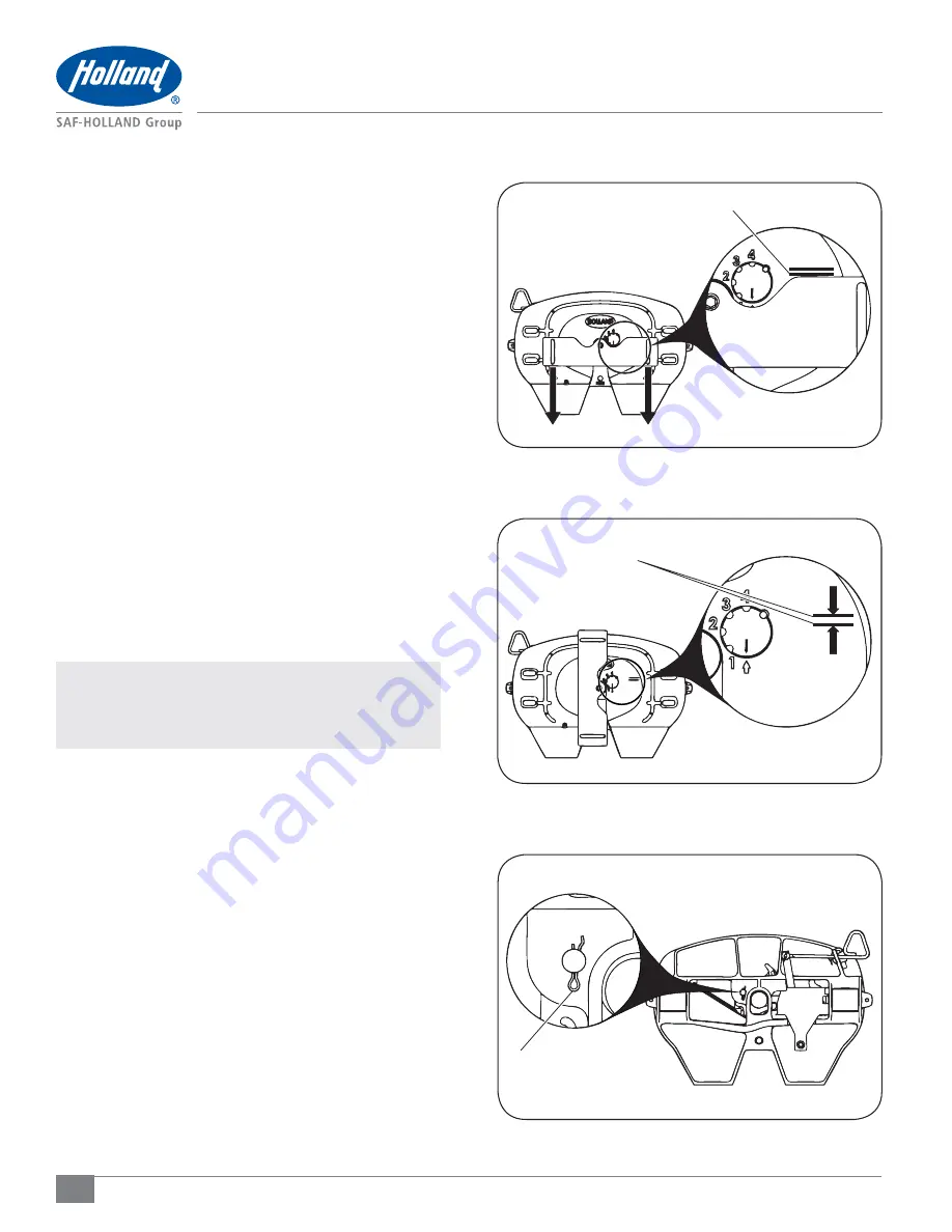
4. Pull the lock tester toward the fifth wheel ramps. Ensure
the lock tester is pressed flat against the surface of the
fifth wheel. Scribe a second line on the surface of the
fifth wheel face along the front edge of the lock tester
(Figure 15)
.
5. Rotate the lock tester out of the way and measure the
distance between the scribed lines. If distance between
lines exceeds 1/8" (3 mm), the lock MUST be adjusted
tighter
(Figure 16)
.
6. To adjust lock:
With the lock tester still locked in the fifth wheel, lift
up on fifth wheel ramps and rotate fifth wheel to its
forward most position (toward the cab).
Remove clinch pin from the bottom of the lock
adjustment pin
(Figure 17)
.
Lift the lock adjustment pin and rotate clockwise to
the next adjustment position shown on the face of fifth
wheel
(Figure 18)
.
Push the lock adjustment pin into fifth wheel in the
new position.
Replace clinch pin.
7. Re-check for free play in the locks by repeating Steps 3-5.
If free play still exceeds 1/8" (3 mm), repeat Step 6 and
rotate lock adjustment pin one more notch.
NOTE:
If free play greater than 1/8" (3 mm) remains
with the lock adjustment pin on the last (fourth)
position, then the fifth wheel should be rebuilt
using rebuild kit RK-FWS-A-L.
MEASURE DISTANCE
BETWEEN LINES
CLINCH PIN
SCRIBE SECOND LINE


