background image

Repair Instructions

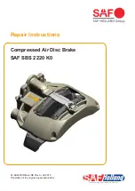
Compressed Air Disc Brake
SAF SBS 2220 K0

XL-SA40001RM-en-DE Rev A • 02.2016

Translation of the original repair instructions

Summary of Contents for SBS 2220 K0

Page 1: ...Repair Instructions Compressed Air Disc Brake SAF SBS 2220 K0 XL SA40001RM en DE Rev A 02 2016 Translation of the original repair instructions ...

Page 2: ...ect to the copyright of SAF HOLLAND GmbH All rights reserved No part of this manual may be reproduced copied or translated in any form or by any means without the prior written permission of SAF HOLLAND GmbH Brand names mentioned in this manual are not identified as such in all cases but they are nevertheless subject to the provisions of trademark legislation The failure of any individual provisio...

Page 3: ...e brake pads 22 6 2 Installing the brake pads 23 6 3 Mounting the wear contacts 25 7 Replacing the pressure fittings 27 7 1 Removing the pressure fittings with bellows 13 27 7 2 Removing and installing the inner seal 22 29 7 3 Mounting the pressure fittings with bellows 13 31 8 Removing and installing the brake calliper 34 8 1 Removing the brake calliper from the carrier 34 8 2 Mounting the brake ...

Page 4: ...ing brake Secure the vehicle with wheel chocks to prevent it from rolling away A loss of pressure in the compressed air brake unit can impair braking efficiency 8 When carrying out work underneath or on the vehicle and especially when working in the engine compartment always switch off the engine and disconnect the battery If circumstances dictate that the engine be running UTMOST CAUTION must be ...

Page 5: ...disc brakes is not permitted SAF HOLLAND service tools have not been designed for use of an impact wrench Use of an impact wrench can damage the service tools and vehicle resulting in a risk of injury 18 Never use compressed air to clean the brake Avoid swirling brake dust 19 Before commissioning the vehicle ensure that all components and the complete brake system are in an orderly condition Weldi...

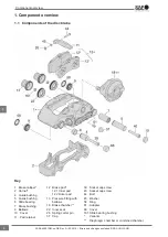
Page 6: ... Brake pad 12 1 Inner pad 12 2 Outer pad 13 Pressure fitting with bellows 18 Brake chamber 22 Inner seal 26 Spring cotter pin 37 Cap 39 Socket cap screw 40 Socket cap screw 44 Bolt 45 Washer 58 Ring 61 Adapter 68 Cover 161 Slide bearing bushing Variants Diaphragm chamber or combined chamber Component overview 6 en XL SA40001RM en DE Rev A 02 2016 Errors and changes excluded SAF HOLLAND ...

Page 7: ...LAND replacement brake discs Use of non approved brake discs is prohibited for safety and liability reasons When replacing brake discs ensure that the correct bolted connections and tightening torques are used SAF HOLLAND recommends that brake discs be replaced axially Brake discs can be obtained from the SAF HOLLAND sales organisation In addition SAF HOLLAND recommends that the brake discs be rep...

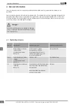
Page 8: ...y or damaged SAF HOLLAND tools resulting from improper use Danger 2 1 Tightening torques Item no Description Tightening torque Width across flats AF Brake calliper on brake carrier of axle 4 socket cap screws M18 x 1 5 From inside to outside Pre tightening 120 Nm Final tightening 450 Nm or 120 Nm pre tightening 60 4 corner multi tooth 24 multi tooth 39 40 Guide bearing on brake calliper 2 socket c...

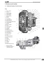
Page 9: ...d pipe 17 Bridge 18 Brake chamber 19 Lever 20 Roller bearing 22 Inner seal 23 Adjuster 24 Retainer 26 Spring cotter pin 27 Compression spring 30 Roller chain 32 Chain sprocket 33 Wear sensor 37 Cap 39 Socket cap screw 40 Socket cap screw 44 Bolt 45 Washer 46 Brake disc 58 Ring 61 Adapter 68 Cover 161 Slide bearing bushing Observe variants Diaphragm chamber or combined chamber Structure and functio...

Page 10: ...clearance is the distance between the brake pad 12 and the brake disc 46 This distance is required to allow the brake disc 46 to run freely unbraked when in the brake released state If the clearance is too large the braking distance may be extended when braking The prescribed clearance has been designed to compensate for operational influences such as Temperature dependent changes to component len...

Page 11: ...ng elements 9 58 and calliper bearing in the slide bearing 6 area must be checked for clearance and damage see Chap 5 3 4 Annually The movement of the brake calliper within the clearance see Chap 5 3 1 and the presence of the cover 10 cap 37 and cover 68 must be checked Note These are minimum intervals Depending on use more frequent component inspection may be required Ensure to observe the inform...

Page 12: ...hten screws nuts and bolts to the prescribed tightening torques see Chap 2 4 Screw threads and threaded holes must be free of lubricants grease and residues of screw locking agent Danger When fitting wheels in accordance with the instructions from the vehicle manufacturer ensure that the wheel has sufficient clearance to the brake calliper otherwise there is a risk of damage to the wheel After com...

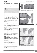
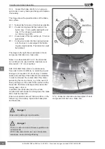
Page 13: ...ced see Fig A Overall thickness of a new brake pad 32 mm B Pad carrier plate 9 mm C Minimum thickness of friction material 2 mm D Absolute minimum thickness of brake pad 11 mm In the event that these minimum thicknesses are reached the brake pads must be replaced Brake discs Measure the thickness of the brake disc at the weakest point note any burrs on the edge of the brake disc Observe the inform...

Page 14: ...nce free under normal conditions i e polishing on pad change is not required D1 occurs only in isolated cases and polishing of the brake discs is advisable in order to increase the contact ratio of the brake pad during the run in process e g in the event of heavy scoring over the entire friction surface of the brake disc Minimum subsequent dimension after turning down 39 mm In addition the informa...

Page 15: ...lace the brake pads and brake discs only axially Danger Wear indicators signal 5 1 6 Depending on the vehicle manufacturer and vehicle type the brakes may be equipped with wear indicators These electrical wear indicators with sensor and cable are positioned on the pad carrier plate The circuit is interrupted when the brake pad wear reaches its limit see Fig 5 1 5a With new pads and new brake disc ...

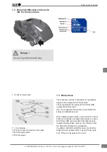
Page 16: ...r on its guide pin in the direction of the centre of the vehicle see Fig 5 2 6 3 Using a suitable tool press the inner brake pad 12 away from the pressure fittings 13 see Fig 5 2 6 1 Sliding the brake calliper backwards and forwards in the guide three times 5 2 6 2 Sliding the brake calliper on its guide pin in the direction of the inner pad 5 2 6 3 Pressing away the inner brake pad 5 2 6 4 Removi...

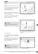
Page 17: ...creas ing clearance 5 2 7 2 Fit the ring spanner or socket to the adapter Actuate the brake 5 to 10 times approx 2 bar In the event of a functional adjustment rotate the ring spanner or socket cyclically in the direction of the arrow see Fig and note below Note As the cycle rate increases the twisting angle or movement of the ring spanner or socket decreases If the ring spanner or socket fails to ...

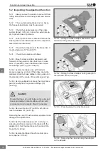
Page 18: ...corporation of the pressure fittings replace the brake pads if necessary Check the contact surfaces in the carrier for incorporation replace the carrier if necessary 5 2 8 4 Check the brake disc For brake discs from SAF HOLLAND see 5 1 For brake discs from other manufacturers observe their information 5 2 8 5 Check the movement of the brake calliper over the entire movement path see 5 3 5 2 8 6 In...

Page 19: ...over the entire calliper guide must be checked see item 5 3 2ff Movement over the entire calliper guide 5 3 2 Remove the brake pads see Chap 6 1 5 3 3 Turn the pressure fittings 13 back fully see Fig 5 3 4 The brake calliper 1 must move over the entire movement path 25 mm see Fig In the event that the brake calliper does not move over the prescribed movement path of 25 mm or fails to move at all t...

Page 20: ...cast pockets in the brake calliper 1 may be used as measuring points see arrow A 5 4 5 Set the dial gauge to zero 5 4 6 Insert a suitable tool e g screwdriver as shown with a length of approx 200 mm between the brake calliper 1 as centred as possible to the carrier 2 and press the brake calliper away in the clearance area with normal force see Fig 5 4 7 Read off the dial gauge Maximum clearance 1 ...

Page 21: ...y to be able to see the bellows clearly see Fig Unscrew the pressure fittings 13 a minimum of 35 to maximum 40 mm or insert a new pad on the outside and unscrew the pressure fittings as far as the disc Caution 5 5 3 The bellows on the pressure fittings 13 must not exhibit any cracks or other damage see Fig Check for proper seating Note The ingress of dirt and moisture into the brake will cause cor...

Page 22: ...s out the bolt 44 see Fig If necessary remove the cable guide plate 104 and wear contacts 101 6 1 3 Remove the cap 37 with the tab see Fig Removing the cap 37 with auxiliary equipment can damage the adjuster seal Caution 6 1 4 Using a ring spanner AF10 turn the adjust er adapter in an anti clockwise direction and fully de adjust the threaded pipes The turning moment of the overload coupling in the...

Page 23: ...rrier plate must be clean and free of residues dirt and moisture Caution 6 2 3 Apply a thin layer of non conductive heat resistant and solid free metal free paste to the guide surfaces of the carrier and to the pad carrier plate Do not use copper paste The paste must not come into contact with the friction surfaces of the pad brake disc or elastomer parts Caution Observe the regulations from the v...

Page 24: ...te and wear contacts see Chap 6 3 6 2 9 Fit the wheels observe the information from the respective vehicle manufacturer Once the brake has been actuated and released it must be possible to turn the wheel hub by hand 6 2 6 Installing the pad retainer 6 2 7 Fitting the washer and spring cotter pin to the bolt 6 2 8 Replacing the cap After completing work on the disc brake always perform a final chec...

Page 25: ...e brake pads 12 and press in as far as they will go see Fig The wear sensors will lock in place Insert the brake pads 12 with pre mounted wear contact set into the pad shaft see Fig see also Chap 6 2 Mount the pad retainer 11 with bolt 44 washer 45 and spring cotter pin 26 see Fig and Chap 6 2 Ensure the correct position of the wear indicator cable 101 see arrows 6 3 1 Mounting the wear contacts 6...

Page 26: ...cable end is not guided in arrow C Mount the cover plate 104 Locate the cover plate 104 on one edge of the pad retainer 11 Ensure the correct position of the retaining lugs of the cover plate 104 see arrow E When radial pressure is applied to the cover plate 104 it will lock into place in the pad retainer 11 see Fig 6 3 4 Locking the cable guide in place 6 3 5 Mounting the wear indicator cable to ...

Page 27: ...ion L2 with the brake calliper removed 7 1 Removing the pressure fittings with bellows 13 Note The pressure fittings 13 can be replaced with the brake calliper installed or removed see Chap 8 With the brake calliper installed 7 1 1 Unscrew the pressure fittings 13 by turning the adapter minimum 35 mm and maximum 40 mm then lever out the bellows with a screwdriv er B 7 Tool composition 7 1 1 Unscre...

Page 28: ... can damage the internal mechanics Danger 7 1 3 Remove the old slide bearing bushing 161 see Fig 7 1 4 Check the seal see arrow X see Fig If the seal X is damaged the brake calliper must be replaced see Chap 8 Note When replacing the pressure fittings with bellows 13 the inner seal 22 must also be replaced see Fig 7 1 2b 7 1 2a Removing the bellows and pressure fittings 7 1 2b Removing the bellows...

Page 29: ...moving and installing the inner seal 22 7 2 1 Unscrew the threaded pipes brake calliper installed 7 2 2 Clean the inner seal area 22 and lever out the inner seal 22 with a screwdriver B see Fig The seal X around the inner seal in the calliper must not become damaged as otherwise the brake calliper will need to be replaced Danger 7 2 3 Clean the seal X see Fig 7 2 4 Screw the threaded pipes 16 onto...

Page 30: ... calliper removed the tool combination L2 should be used with the tool components T03 T04 T09 see Chap 7 7 2 11 Move the tool combination L2 into the position shown Note The slide bearing bushing must not be fitted yet 7 2 12 Secure the tool component T09 with the second open end wrench AF27 against twisting and press in the inner seal 22 as far as it will go by unscrewing T03 7 2 13 Remove the to...

Page 31: ...16 and fit the pressure fitting with bellows 13 to the base of the threaded pipe 16 7 3 4 Position the tool combination E1 and mount the pressure fitting 13 to the threaded pipe by unscrewing the tool component T03 Note The tool component T55 is not required for this mounting step 7 3 5 Turn the tool combination E1 Note Before performing the next step insert the tool component T55 into the tool co...

Page 32: ... 161 to the threaded pipes 16 and fit the pressure fitting with bellows 13 to the base of the threaded pipe 16 see Chap 7 3 3 7 3 9 Position the tool combination E2 and mount the pressure fitting 13 to the threaded pipe by unscrewing the tool component T03 Note In this step the tool component T56 must be inserted into the tool component T28 see Fig 7 3 10 Remove the tool combination E2 7 3 8 Press...

Page 33: ...n the bellows of the pressure fitting 13 see Fig 7 3 14 It must be possible to turn the pressure fittings 13 slightly in both directions pay attention to the bellows see Fig 7 3 11 Tool component E3 7 3 13 Pressing in the bellows of the pressure fitting with the long tool combination E3 7 3 14 Pressure fittings must rotate slightly in both directions Replacing the pressure fitting 33 en XL SA40001...

Page 34: ... the cover 10 in the centre with a suitable tool see Fig The cover 10 can then shift by approx 10 mm Punch the cover 10 in the centre Do not drive the levering tool between the calliper bore and cover 10 as this can damage the bore Caution 8 1 4 Lever out the cover 10 with a suitable tool see Fig Check the bearing area of the calliper bore for corrosion and repair with a suitable guide and seal ki...

Page 35: ...e loosening the socket cap screws 39 40 secure the brake calliper 1 against falling Danger 8 1 6 Unscrew the socket cap screws 39 and 40 see Fig Hold the brake calliper 1 on the outside only never place the fingers between the brake calliper 1 and carrier 2 2 Never attach a hoisting device to the pad retainer 11 as this can damage the pad retainer The brake calliper must not be opened or disassemb...

Page 36: ...r place the fingers between the brake calliper 1 and carrier 2 Never attach a hoisting device to the pad retainer 11 as this can damage the pad retainer Danger 8 2 2 Slide the guide bushings 4 5 from outside in the direction of the pad shaft into the guide bear ing 8 2 3 Check the correct seating of the inner bel lows 9 and the rings 58 on the guide bushings 4 5 see Fig 8 2 1 8 2 2 Observe the typ...

Page 37: ...nts The cover may only be fitted once the brake calliper has been fully bolted to the carrier see Chap 8 2 Caution Cover variant 10 long bearing side The seating surface of the cover 10 in the calliper bore must be free of grease 8 2 10 Clean the new cover 10 thoroughly Clean the inside area of the press in tool H and place the cover inside see Fig 8 2 11 Ensure that the flat surface and chamfer o...

Page 38: ...horoughly Clean the inside area of the press in tool M and place the cover inside see Fig 8 2 14 Ensure that the flat surface and chamfer of the calliper bore are not damaged see arrow Position the press in tool M with cover 68 on the flat surface of the calliper bore see Fig Note Do not tilt the tool The inner bellows 9 must compressed as otherwise the movement of the brake calliper will be restr...

Page 39: ...ke cal liper to the axle use only new screws observe the prescribed tightening torques Note When mounting to the vehicle axle the regulations from the respective vehicle manufacturer must be observed 8 2 20 Install the brake pads see Chap 6 2 8 2 21 Check the adjustment function see Chap 5 2 8 2 22 Fit the diaphragm or combined chamber see Chap 11 2 or 11 4 Then adjust the clear ance See Chap 5 2 ...

Page 40: ...ing the bushing 7 In order to simplify the composition of tools and components they are allocated item numbers see also Chap 2 1 For removal and installation use the tool combination for inserting and caulking the bushing 7 tool combination D The tool combination D can also be used for caulking the bushing 7 9 2 1 Clean the spot face arrow A and the bush ing 7 see Fig 9 1 2 9 1 4 Removing the part...

Page 41: ... Turn back the brass nut T14 on the spindle T13 as far as it will go and position the flange T08 Insert the new bushing 7 onto the embossed part T16 and locate on the calliper bore via the pad shaft see Fig 9 2 4 Move the tool combination D for inserting and caulking the bushing 7 into position see Fig 9 2 5 Screw the spindle T13 into the embossed part T16 by hand as far as it will go Ensure that ...

Page 42: ...d in the repair kit 9 3 Replacing the slide bearing 6 on the short bearing side In order to simplify the composition of tools and components they are allocated item numbers see Chap 2 1 9 3 1 To replace the slide bearing 6 use the tool combination 5 see Fig Pulling out the slide bearing 6 9 3 2 Remove the guide bushing 4 9 3 3 Clean the bearing in the pad shaft area 9 3 4 Position the tool combina...

Page 43: ...ig If the torque during the insertion process is 4 Nm or 25 Nm the calliper must be replaced Do not turn at the nut T14 as this can cause the slide bearing 6 to twist Caution 9 3 11 Remove the mounting tool 9 4 Installing the bellows 9 In order to simplify the composition of tools and components they are allocated item numbers see Chap 2 1 9 4 1 To install the bellows 9 use the tool com bination C...

Page 44: ...i nation C 9 4 5 Ensure the correct seating of the bel lows 9 Perform a tension test see Fig 9 4 5 9 4 6 Smear the brass bushing 7 and slide bearing 6 with white grease supplied in the repair kit 9 4 7 Install the guide bushings 4 5 see Fig 9 2 4 9 4 3 Inserting the new bellows with the tool combination C into the bore and hand tightening T10 9 4 4 Inserting with max torque of 8 Nm 9 4 5 Ensuring ...

Page 45: ...ig 9 4 10 Push the ring 58 on to secure the bel lows 9 in the groove of the guide bushing 4 5 see Fig 9 4 11 Mount the brake calliper to the carrier see Chap 8 2 9 4 8 Inserting the bellows into the groove arrow A 9 4 10 Securing the bellows with ring Repairing the brake calliper bearing 45 en XL SA40001RM en DE Rev A 02 2016 Errors and changes excluded SAF HOLLAND ...

Page 46: ...he regulations from the vehicle manufacturer 10 2 1 The mating surface and flange surface see arrow B Must be free of dirt and corrosion Must not exhibit any damage Must be flat Ensure that no dirt or water can penetrate the inner mechanism of the brake 10 2 2 Before inserting the new diaphragm chamber smear the spherical bearing in the lever 19 and the mating surface B with white grease supplied ...

Page 47: ...chamber secure the vehicle to prevent it from rolling away Danger 10 3 1 Release the parking brake 10 3 2 Move the spring mechanism emergency release spindle arrow D to the release position observe the regulations from the vehicle manufac turer see Fig 10 3 3 Actuate the parking brake 10 3 4 Unscrew the air connections from the com bined chamber 18 the connection line must be depressurised 10 3 5 ...

Page 48: ...ow C must be free of dirt and moisture If the seal protrusion is 3 mm the combined brake chamber must be replaced 10 4 4 Locate the combined chamber see Fig Note To prevent the combined chamber from tilting whilst being tightened the new self locking hex nuts of the combined chamber must be hand tightened symmetrically with a suitable tool 10 4 5 Tighten both self locking hex nuts in accord ance w...

Page 49: ...aße 26 D 63856 Bessenbach Emergency hotline 49 6095 301 247 Customer Service 49 6095 301 602 Fax 49 6095 301 259 service safholland de www safholland com XL SA40001RM en DE Rev A 02 2016 Errors and changes excluded SAF HOLLAND ...

Reviews: