Check the adjustment thread (16)
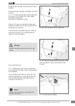
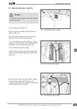
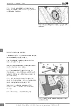
7.1.5 Insert the new brake pad (12
2
) into the out-
er calliper shaft so that the threaded pipes cannot
be unscrewed from the bridge. Unscrew the thread-
ed pipes by turning the adapter (61) (see Fig.).
Do not fully unscrew the threaded pipes (16) from
the bridge as this can impair synchronisation,
necessitating complete replacement of the brake
calliper.
Danger !
With the brake calliper removed:
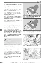
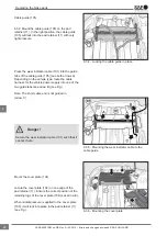
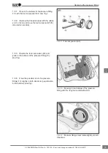
7.1.6 If the brake calliper has been removed or is
on the workbench, a suitable spacer (S) (=70 mm)
must be inserted when unscrewing the threaded
pipes (16) to prevent the threaded pipes (16) from
being fully removed (see Fig.).
Check for corrosion and damage whilst unscrewing
the thread of the threaded pipes (16). If ingressed
water or corrosion is detected, the brake calliper
must be replaced (see Chap. 8).
7.2 Removing and installing the inner
seal (22)
7.2.1 Unscrew the threaded pipes (brake calliper
installed)
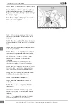
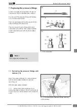
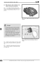
7.2.2 Clean the inner seal area (22) and lever out
the inner seal (22) with a screwdriver (B) (see Fig.).
The seal (X) around the inner seal in the calliper
must not become damaged as otherwise the
brake calliper will need to be replaced.
Danger !
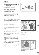
7.2.3 Clean the seal (X) (see Fig.).
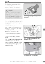
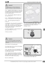
7.2.4 Screw the threaded pipes (16) onto the
brake disc (46) by turning the adapter (61) (screw
out max. 40 mm only) (see Fig.).
7.2.5 Smear the threaded pipes with white
grease (supplied in the repair kit) and then turn
back as far as it will go (see Fig.).
7.2.6 Apply the new inner seal (22) to the thread-
ed pipe (16).
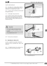
7.1.5 - Unscrewing the threaded pipes (brake
calliper installed)
7.1.6 - Unscrewing the threaded pipes (brake
calliper removed)
7.2.2 - Cleaning the area, levering out the inner
seal
7.2.3 - 7.2.5 - Screw out the threaded pipes and
smear with white grease
Replacing the pressure fittings
29
en
XL-SA40001RM-en-DE Rev A • 02.2016 • Errors and changes excluded © SAF-HOLLAND

