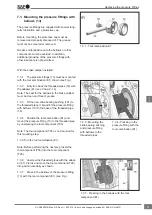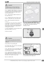
9.4.8 Insert the bellows (9) into the groove (ar-
row A) (see Fig.).
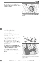
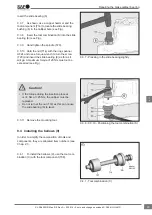
9.4.9 Check that the ring on the bellows is prop-
erly positioned in the groove of the guide bushing
(see Fig.).
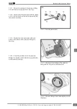
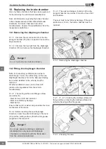
9.4.10 Push the ring (58) on to secure the bel-
lows (9) in the groove of the guide bushing (4, 5)
(see Fig.).
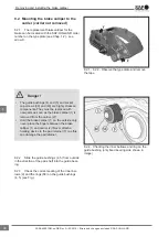
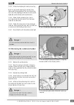
9.4.11 Mount the brake calliper to the carrier
(see Chap. 8.2).
9.4.8 - Inserting the bellows into the groove
(arrow A)
9.4.10 - Securing the bellows with ring
Repairing the brake calliper bearing
45
en
XL-SA40001RM-en-DE Rev A • 02.2016 • Errors and changes excluded © SAF-HOLLAND

