22
D) Installation instructions
Fitting the folding bellows
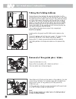
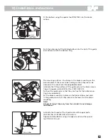
Remove the securing ring from the pressure plate. Next, lay the
pressure plate on a flat surface with the required tools on top. Place
the conical part of the special tool on top. Fit the protection springs
with their small ends at the bottom onto their position on top of
the special tool. Fit the securing ring into position on the folding
bellows. Using the outer part of the special tool, push the folding
bellows/securing ring unit into position onto the pressure plate.
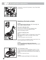
Remove both parts of the special tool. Re-fit the securing ring. Do
not remove the special tool P/N 81926.
Check whether the adjuster screws are fully screwed back.
Note! Do not tighten!
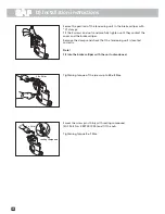
Finally position the special tool P/N 81926 onto its place on the
cover.
Press in the bellows unit into the cover using a "G" clamp. Use the
special tool P/N 81928 in the adjuster rod hole as support.
Remove the "G" clamp and special tool P/N 81926 and 81928.
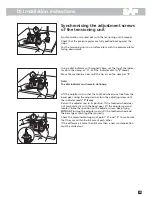
The folding bellows and the pressure plate must be pressed fully
home.
Removal of the guide pins / slides
Secure the disc brakes in a vice.
Remove the 4 cover plates with a hammer and chisel.
The cover plates may not be used again.
Should any part of the cover plate remain in the guide pin, it can be
used with e.g. the help of an inside bearing puller (standard tool).
Remove the 4 screws of the guide pins with the special tool
(TORX E 18 nut).
Set the guide pins so far back using a backwards and forwards moti-
on so that the brake calliper can be removed.
Note!
Do not use pipe wrenches or similar tools as the folding bellows'
surfaces could be damaged.
sleeve
insert
O-ring
81926
81928
Summary of Contents for SK 1000 ET 120
Page 4: ...NOTIZEN NOTES NOTE 4 ...
Page 33: ...NOTIZEN NOTES NOTE 33 ...

