B - MISE EN SERVICE
STARTING UP
1. DESCRIPTION
DESCRIPTION
Le poste est livré emballé dans un carton.
The set is delivered mounted in a cardboard crate.
+
Ouvrir l'emballage.
+
Open the packing.
+
Dégager le poste du socle bois.
+
Remove it from the pallet.
+
Il est prêt à être équipé de ses options et
raccordé.
+
It is ready to be equipped with its options and to
be connected.
Un support de torche est livré avec le générateur.
Il peut être fixé sur un côté du générateur ou à
proximité de l’opérateur. Il permet de poser la torche
TIG après utilisation.
A torch support is delivered with the power source.
It can be fixed on one side of the power source or
near the operator. It allows the torch to be set after
use.
a) Couplage de la tension et de la fréquence au réseau
Coupling of voltage and frequency to mains
+
Tension : version standard
+
Voltage : standard version
!
ATTENTION
: avant de raccorder le câble
au réseau, il est essentiel de :
+
vérifier que le point de branchement n'est pas
sous tension,
+
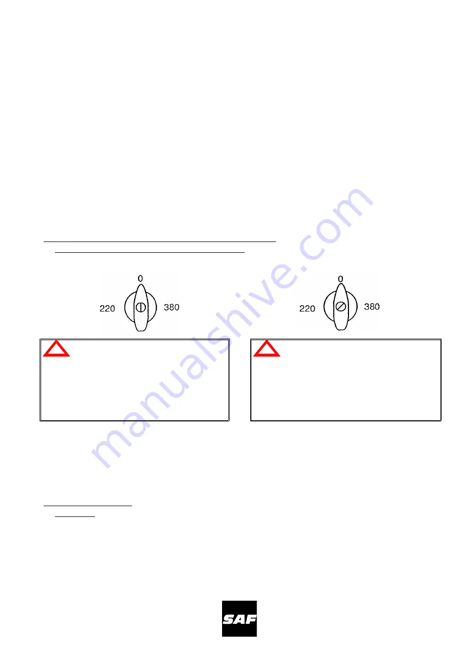
vérifier que le couplage primaire correspond à
la tension du réseau, vérifier que le
commutateur M/A est sur la position
"
0
"
.
!
WARNING
: before connecting the cable
to the mains, it is essential to :
+
check that there is no power at the connecting
point,
+
check that the primary connection corresponds
to the mains voltage, check that the ON/OFF
switch is set to the position
"
0
"
.
+
Fréquence :
+
Frequency :
ð
le poste est livré couplé en 50 Hz
ð
the set is delivered connected for 50 Hz
ð
le couplage s'effectue sur le bornier B2 de
TA1 (accessible en démontant le toit)
ð
the connection takes place on terminal board
B2 of TA1(remove the top to access)
ð
couplage 50 Hz - strapp A/B
ð
50 Hz connection - strap A/B
ð
couplage 60 Hz - strapp A/27 V.
ð
60 Hz connection - strap A/27 V.
b) Mise sous tension
Power on
Mettre sous tension le réseau et tourner le
commutateur en position de marche.
Turn on the mains power and turn the switch to the
"ON" position.
Le voyant vert de mise en marche s'allume, si le
voyant orange s'allume le poste est en position
sécurité.
The green signal lamp indicating "starting up" lights
up, if the orange lamp is lighted, the power source is
on safety mode.
B
- 21
NERTINOX
250
P
PONTICELLI
Summary of Contents for NERTINOX 250 P PONTICELLI
Page 5: ...NERTINOX 250P PONTICELLI 3 ...
Page 17: ...CONSIGNES DE SECURITE SAFETY INSTRUCTIONS NERTINOX 250P PONTICELLI A 15 ...
Page 20: ...CONSIGNES DE SECURITE SAFETY INSTRUCTIONS A 18 NERTINOX 250P PONTICELLI ...
Page 22: ...CONSIGNES DE SECURITE SAFETY INSTRUCTIONS A 20 NERTINOX 250P PONTICELLI ...
Page 26: ...CONSIGNES DE SECURITE SAFETY INSTRUCTIONS B 24 NERTINOX 250P PONTICELLI ...
Page 34: ...3 SCHEMA DE PRINCIPE MAIN DIAGRAM 4 PRINCIPE DE FONCTIONNEMENT E 32 NERTINOX 250P PONTICELLI ...
Page 38: ...b Commande de cycle TIG en 2 temps E 36 NERTINOX 250P PONTICELLI ...
Page 39: ...Cycle command of TIG in 2 stages NERTINOX 250P PONTICELLI F E 37 ...
Page 40: ...c Commande de cycle en 4 temps E 38 NERTINOX 250P PONTICELLI ...
Page 41: ...Cycle command of TIG in 4 stages NERTINOX 250P PONTICELLI F E 39 ...
Page 42: ...d Distribution des alimentations et leurs contrôles E 40 NERTINOX 250P PONTICELLI ...
Page 45: ... Soudage électrode Electrode welding NERTINOX 250P PONTICELLI F E 43 ...
Page 46: ... TIG Cycle 2 temps TIG 2 stage cycle E 44 NERTINOX 250P PONTICELLI ...
Page 47: ... TIG Cycle 4 temps TIG 4 stage cycle NERTINOX 250P PONTICELLI F E 45 ...
Page 48: ...b Amorçage de l arc Electrode enrobée E 46 NERTINOX 250P PONTICELLI ...
Page 49: ...b Arc ignition Coated electrode NERTINOX 250P PONTICELLI F E 47 ...
Page 50: ...c Soudage TIG amorçage de l arc E 48 NERTINOX 250P PONTICELLI ...
Page 51: ...c TIG welding arc ignition NERTINOX 250P PONTICELLI F E 49 ...
Page 52: ...d Soudage TIG arrêt de soudage E 50 NERTINOX 250P PONTICELLI ...
Page 53: ...d TIG welding welding interruption NERTINOX 250P PONTICELLI F E 51 ...
Page 69: ......
Page 72: ...b Nomenclature Part list E 70 NERTINOX 250P PONTICELLI ...
Page 73: ...NERTINOX 250P PONTICELLI G E 71 ...
Page 75: ...NERTINOX 250P PONTICELLI G E 73 ...
Page 77: ...b Implantation des composants Components layout NERTINOX 250P PONTICELLI G E 75 ...
Page 78: ...c Nomenclature Part list E 76 NERTINOX 250P PONTICELLI ...
Page 79: ...NERTINOX 250P PONTICELLI G E 77 ...
Page 81: ...b Implantation des composants Components layout NERTINOX 250P PONTICELLI G E 79 ...
Page 83: ...b Implantation des composants Components layout NERTINOX 250P PONTICELLI G E 81 ...
Page 85: ...b Implantation des composants Components layout NERTINOX 250P PONTICELLI G E 83 ...


