15
XL-SA20018UM-en-US Rev H · 2017-12-14 · Amendments and Errors Reserved · © SAF-HOLLAND, Inc., SAF-HOLLAND, HOLLAND, SAF, and logos are trademarks of
SAF-HOLLAND S.A., SAF-HOLLAND GmbH, and SAF-HOLLAND, Inc.
Disc Brake Servicing
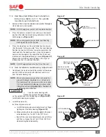
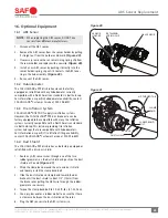
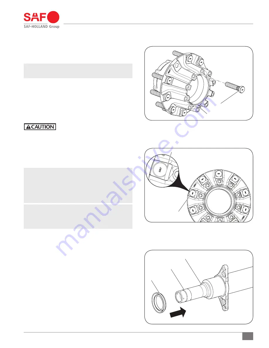
Figure 23
HUB SEAL
KEYWAY
AXLE SPINDLE INNER SHOULDER
10. Hub Wheel Bolt Servicing
When replacing the wheel bolts, refer to the rotor removal
instructions described in Section 9.
NOTE:
NOT all bolts may need to be replaced. ONLY replace
bolts that are damaged or in need of replacement.
1. Remove the wheel bolts by pressing them out of the head
unit and discard
(Figure 21).
2. Install new wheel bolts by pressing them into the head unit.
3. For INTEGRAL
®
rotor hub, ensure correct alignment of the
bolts during installation, position the flat side of each
wheel bolt head so that it is facing the center of the hub
(Figure 22)
.
DO NOT hit steel parts with a steel
hammer as parts could break, sending
flying steel fragments in any direction
creating a hazard which, if not avoided,
could result in minor to moderate injury.
11. Seal, Bearing, and Hub Installation
and Adjustment
IMPORTANT:
DO NOT mix oil and grease wheel end
lubricants. All SAF-HOLLAND
®
P89 Disc Brake
wheel ends can be serviced with oil or grease.
Before servicing the SAF-HOLLAND
®
P89 wheel
end with oil, all grease MUST be cleaned with
appropriate solvent from the bearings and hub.
NOTE:
Although all SAF-HOLLAND
®
P89 Disc Brake wheel
ends are manufactured with spindle mounted wheel
seals they can be serviced with either spindle or
hub mounted seals.
11.1 Spindle mounted wheel seal Installation
instructions. (Refer to 11.2 for hub mounted
wheel seal instructions)
1. Before installing the wheel seal on the axle spindle, inspect
the machined spindle seal surface for nicks, scratches, burrs
or marks. If needed, use crocus cloth or emery cloth to
repair any damaged areas.
2. Clean the threads and keyway thoroughly with a wire
brush to avoid false bearing adjustments and to avoid
introduction of contaminants into the lubricant cavity.
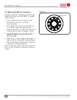
Figure 22
WHEEL BOLTS,
TEN (10)
FLAT SIDE OF BOLT HEAD
Figure 21
WHEEL BOLTS (10)
HEAD UNIT


